
|
Subaru Car Manual & Air Bag Light Diagnosishttp://www.berklix.com/~jhs/txt/airbag/by Julian H. StaceyDEUTSCH via translate . google . com - http://www.berklix.net/trans/Legacy II (ie 2) Station Wagon (BG) BGC/510 1998 ,
BG is a [Station] Wagon (American) = Estate (British)
= Kombi (German)
BD is a Sedan (American) = Saloon (British), ("Trend" just added a few optional frills to Legacy, not significant). Index (Deutsch=Verzeichnis)
Caution: Some Local Links Fail As Data not yet exported
Some local symbolic links will
not work with a browser from
or even locally on editor''s master site from
as the .pdf are not [as yet] on line served by an httpd
server.
For my (jhs@) local viewing, it works clicking links from this in in URL box: file:///home/jhs/public_html/txt/airbag/index.html Models
Which PDF Manual ?My Intro
My (jhs@) car (Subaru Legacy
1998) air bag warning light was iffy, then came on solid.
Subaru Dealers had failed to fix several times { Retired
first dealer seemed to improve it, but he wasn''t happy it
would last, & he didn''t say how he''d fixed it (trade
secret or more likely foreign language limitations) (I noted
at 2019-10 that the cable reel (informally: Clock Spring)
seal is broken). 2nd dealer had no time on 1 or 2 services,
then mechanic admitted he did not like doing electrics}. ( Pages=4442_121M_liberty_1998_2003.pdf
Page=3599 of calls this "Roll connector" )
Battery Disconnect
I (jhs@) disconnected battery,
left it to stand, touched brake pedals in case any
electrolytics anywhere in car might be storing charge.
Subaru dealers tell me Subarus do not have a supplementary 2nd battery, unlike some other manufacturers example BMW Static Discharge Protection
My (jhs@) synthetic material
shirts & non leather footwear can give static shocks
Wonder if bags probably blow on real current to heat
explosive, or can also blow just on voltage (like silicon
chips) ? - so I (jhs@)
grounded myself to wheel chassis before removing bag.
Name SRS & Takata
"SRS Airbag" just means "Supplementary Restraint System", ie
they expect safety belt to have held your body back in a
crash before the bag explodes in your face . SRS is not a
trade name (as I had falsely assumed it was), so seeing "SRS"
does not mean you don''t have a Takata air bag, Takata are
bad news:
How To Videos
There are Lots of How To videos on YouTube.com, examples:
References Elsewhere on web (alphabetic)
Reconstructing Manuals - Which ? + Sorting & merging a myriad of tiny PDFs
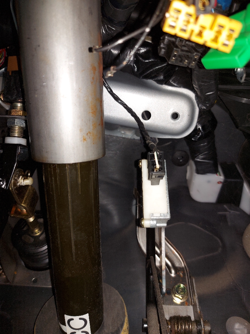
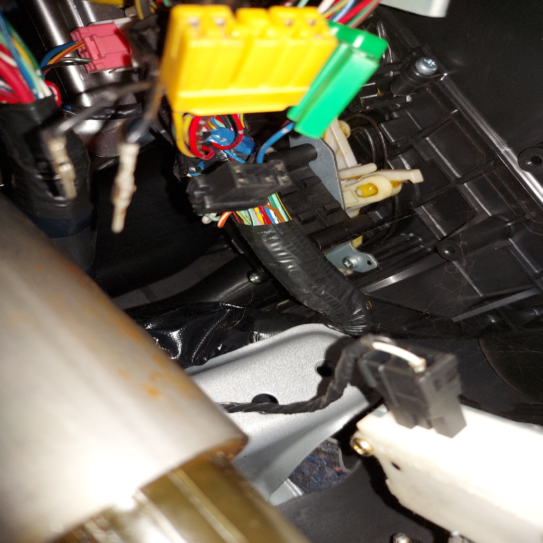
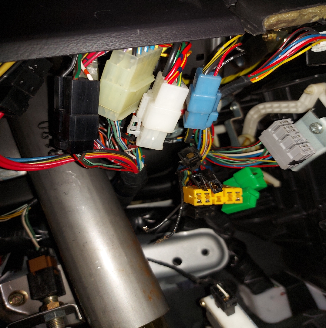
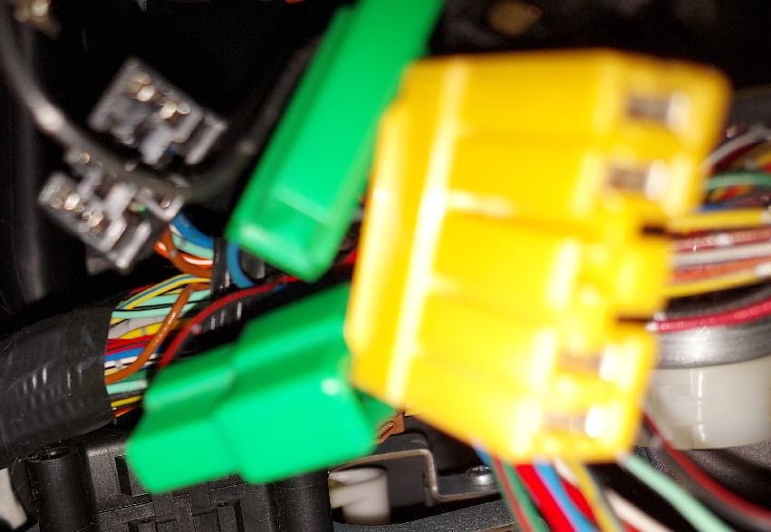
ConnectorsA list under the dashboard during dis-assembly,
There are Two Alternate Data Link Connectors
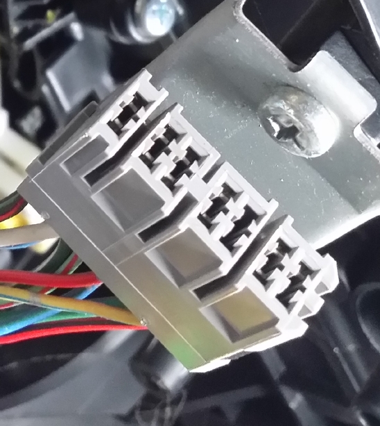
Check Connector [ - 'U' Connector ]
"Diagnosis Connector" is a name used for at least Two Different connectors - So - Which ?
Index of phrase "Diagnosis Connector" : in Pages=2436_86M_1998.pdf - 39 Matches
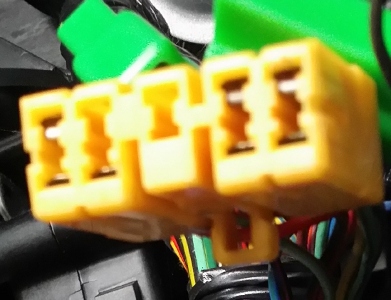
"Diagnosis
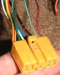
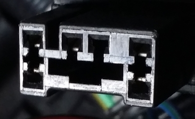
Connector" (6 Pin Black B82 U-Shape)
Name from: |
| Trouble Codes | Check parts | Index. No. |
| 11 |
|
|
| 12 |
|
|
| 22 |
|
|
ECM (ECU Engine Control Module / Unit / Computer)
ECM (ECU Engine Control Module / Unit / Computer) Connector B84 Pins
Discrepancy in Number Of Pins
26 Pins in the range 1-96 are Unlisted in circuit diagrams.
86 pins protrude from My (jhs@) ECM (ECU Engine Control Module / Unit / Computer).
Building a list of all B84 Pin Numbers & colours
Colours From Page=2283 Section=6-3_[D1A0] (Pages=2436_86M_1998.pdf)
| Color code | Color |
| L | Blue |
| B | Black |
| Y | Yellow |
| G | Green |
| R | Red |
| W | White |
| Br | Brown |
| Lg | Light green |
| Gr | Gray |
| P | Pink |
| Or | Orange |
| Lb | Light Blue |
| V | Violet |
| SA | Sealed (Inner) |
| SB | Sealed (Outer) |
Back To Index
Pins Numbers from Section 6-3 starts at Page 2281 of Pages=2436_86M_1998.pdf
| Page | Footer | Pin | Colour | |
| 2291 | 11 | Abbreviation | ||
| 2304 | 24 | 42 | BW=Black+White | |
| 2304 | 24 | 46 | BW=Black+White | |
| 2304 | 24 | 69 | BY=Black+Yellow | |
| 2304 | 24 | 19 | BW=Black+White | |
| 2304 | 24 | 95 | BY=Black+Yellow | |
| 2304 | 24 | 94 | B=Black | |
| 2304 | 24 | 17 | BR=Black+Red | |
| 2304 | 24 | 81 | (MT) BW=Black+White | |
| 2304 | 24 | 18 | BR=Black+Red | |
| 2304 | 24 | 75 | (Without TCS) BR=Black+Red | |
|
|
|
|
|
|
| 2308 | 28 | 19 | BW=Black+White | |
| 2308 | 28 | 42 | BW=Black+White | |
| 2308 | 28 | 69 | BY=Black+Yellow | |
| 2308 | 28 | 46 | BW=Black+White | |
| 2308 | 28 | 95 | BY=Black+Yellow | |
| 2308 | 28 | 94 | B=Black | |
| 2308 | 28 | 17 | BR=Black+Red | |
| 2308 | 28 | 18 | BR=Black+Red | |
| 2308 | 28 | 75 | BR=Black+Red | |
|
|
|
|
|
|
| 2309 | 29 | Airbag Control Module AB6 | ||
|
|
|
|
|
|
| 2310 | 30 | 31 | LOr=Blue+Orange | |
| 2310 | 30 | 60 | BrY=Brown+Yellow | |
|
|
|
|
|
|
| 2311 | 31 | 31 | LOr=Blue+Orange | |
| 2311 | 31 | 60 | BrY=Brown+Yellow | |
|
|
|
|
|
|
| 2315 | 35 | 80 | P=Pink | |
| 2315 | 35 | 79 | L=Blue | |
| 2315 | 35 | 47 | GOr=Green+Orange | |
| 2315 | 35 | 64 | BL=Black+Blue | |
| 2315 | 35 | 6 | Wb=White+Black | |
| 2315 | 35 | 21 | R=Red | |
| 2315 | 35 | 20 | RY=Red+Yellow | |
|
|
|
|
|
|
| 2317 | 37 | 80 | P=Pink | |
| 2317 | 37 | 79 | L=Blue | |
| 2317 | 37 | 47 | GOr=Green+Orange | |
| 2317 | 37 | 64 | BL=Black+Blue | |
| 2317 | 37 | 6 | Wb=White+Black | |
| 2317 | 37 | 21 | R=Red | |
| 2317 | 37 | 20 | RY=Red+Yellow | |
|
|
|
|
|
|
| 2331 | 51 | 80 | P=Pink | |
| 2331 | 51 | 47 | GOr=Green+Orange | |
| 2331 | 51 | 79 | L=Blue | |
| 2331 | 51 | 61 | Light green+Black | |
| 2331 | 51 | 76 | YB=Yellow+Black | |
| 2331 | 51 | 75 | *3 | |
| 2331 | 51 | 77 | Or=Orange | |
| 2331 6-3 [D6M1] TAIWAN MODEL | 51 | 93 | OrW=Orange+White | K Line - ODB2 service connector |
| 2331 | 51 | 23 | B=Black | |
| 2331 | 51 | 38 | W=White | |
| 2331 | 51 | 24 | B=Black | |
| 2331 | 51 | 37 | WL=White+Blue | |
| 2331 | 51 | 15 | YW=Yellow+White | |
|
|
|
|
|
|
| 2332 | 52 | 56 | BG=Black+Green | |
| 2332 | 52 | 26 | G=Green | |
| 2332 | 52 | 20 | RY=Red+Yellow | |
| 2332 | 52 | 21 | R=Red | |
| 2332 | 52 | 6 | Wb=White+Black | |
| 2332 | 52 | 3 | W=White | |
| 2332 | 52 | 22 | BY=Black+Yellow | |
| 2332 | 52 | 71 | BP=Black+Pink | |
| 2332 | 52 | 5 | W=White | |
| 2332 | 52 | 57 | SB | |
| 2332 | 52 | 53 | P=Pink | |
| 2332 | 52 | 41 | YL=Yellow+Blue | |
| 2332 | 52 | 40 | YV=Yellow+Violet | |
| 2332 | 52 | 17 | BR=Black+Red | |
| 2332 | 52 | 18 | BR=Black+Red | |
| 2332 | 52 | 94 | B=Black | |
| 2332 | 52 | 69 | BY=Black+Yellow | |
| 2332 | 52 | 95 | BY=Black+Yellow | |
| 2332 | 52 | 19 | BW=Black+White | |
| 2332 | 52 | 42 | BW=Black+White | |
| 2332 | 52 | 46 | BW=Black+White | |
| 2332 | 52 | 81 | BW=Black+White | |
|
|
|
|
|
|
| 2333 | 53 | 54 | SB | |
| 2333 | 53 | 29 | B=Black | |
| 2333 | 53 | 8 | W=White | |
| 2333 | 53 | 28 | R=Red | |
| 2333 | 53 | 7 | G=Green | |
| 2333 | 53 | 16 | LB=Blue+Black | |
| 2333 | 53 | 44 | LR=Blue+Red | |
| 2333 | 53 | 70 | Lg=Light green | |
| 2333 | 53 | 96 | Br | |
| 2333 | 53 | 14 | B=Black | |
| 2333 | 53 | 13 | WY=White+Yellow | |
| 2333 | 53 | 72 | WL=White+Blue | |
|
|
|
|
|
|
| 2334 | 54 | 35 | BrY=Brown+Yellow | |
| 2334 | 54 | 27 | BrW | |
| 2334 | 54 | 25 | RL=Red+Blue | |
| 2334 | 54 | 10 | Light green+Black | |
| 2334 | 54 | 4 | YL=Yellow+Blue | |
| 2334 | 54 | 32 | V | |
| 2334 | 54 | 63 | Lg=Light green | |
| 2334 | 54 | 83 | GB=Green+Black | |
| 2334 | 54 | 58 | RG=Red+Green | |
| 2334 | 54 | 64 | BL=Black+Blue | |
| 2334 | 54 | 39 | R=Red | |
| 2334 | 54 | 92 | GW=Green+White | |
| 2334 | 54 | 91 | Lg=Light green | |
| 2334 | 54 | 84 | LG=Blue+Green | |
| 2334 | 54 | 31 | LOr=Blue+Orange | |
| 2334 | 54 | 60 | BrY=Brown+Yellow | |
| 2334 | 54 | 74 | RL=Red+Blue | |
| 2334 | 54 | 73 | Green+Red | |
| 2334 | 54 | 1 | YL=Yellow+Blue | |
| 2334 | 54 | 2 | YL=Yellow+Blue | |
| 2334 | 54 | 85 | Yellow | |
| 2334 | 54 | 86 | RY=Red+Yellow | |
| 2334 | 54 | 82 | *2 | |
|
|
|
|
|
|
| 2335 | 55 | 80 | P=Pink | |
| 2335 | 55 | 47 | GOr=Green+Orange | |
| 2335 | 55 | 79 | L=Blue | |
| 2335 | 55 | 61 | Light green+Black | |
| 2335 | 55 | 76 | YB=Yellow+Black | |
| 2335 | 55 | 75 | *3 | |
| 2335 | 55 | 77 | Or=Orange | |
| 2335 6-3 [D6M2] LHD EXCEPT TAIWAN MODEL | 55 | 93 | OrW=Orange+White | K Line - ODB2 service connector |
| 2335 | 55 | 23 | B=Black | |
| 2335 | 55 | 38 | W=White | |
| 2335 | 55 | 24 | B=Black | |
| 2335 | 55 | 37 | WL=White+Blue | |
| 2335 | 55 | 15 | YW=Yellow+White | |
|
|
|
|
|
|
| 2336 | 56 | 56 | BG=Black+Green | |
| 2336 | 56 | 26 | G=Green | |
| 2336 | 56 | 20 | RY=Red+Yellow | |
| 2336 | 56 | 21 | R=Red | |
| 2336 | 56 | 6 | Wb=White+Black | |
| 2336 | 56 | 3 | W=White | |
| 2336 | 56 | 22 | BY=Black+Yellow | |
| 2336 | 56 | 71 | BP=Black+Pink | |
| 2336 | 56 | 5 | W=White | |
| 2336 | 56 | 57 | SB=Sealed (Outer) | |
| 2336 | 56 | 53 | P=Pink | |
| 2336 | 56 | 41 | YL=Yellow+Blue | |
| 2336 | 56 | 40 | YV=Yellow+Violet | |
| 2336 | 56 | 17 | BR=Black+Red | |
| 2336 | 56 | 18 | BR=Black+Red | |
| 2336 | 56 | 94 | B=Black | |
| 2336 | 56 | 69 | BY=Black+Yellow | |
| 2336 | 56 | 95 | BY=Black+Yellow | |
| 2336 | 56 | 19 | BW=Black+White | |
| 2336 | 56 | 42 | BW=Black+White | |
| 2336 | 56 | 46 | BW=Black+White | |
| 2336 | 56 | 81 | BW=Black+White | |
|
|
|
|
|
|
| 2337 | 57 | 54 | SB=Sealed (Outer) | |
| 2337 | 57 | 29 | B=Black | |
| 2337 | 57 | 8 | W=White | |
| 2337 | 57 | 28 | R=Red | |
| 2337 | 57 | 7 | G=Green | |
| 2337 | 57 | 16 | LB=Blue+Black | |
| 2337 | 57 | 44 | LR=Blue+Red | |
| 2337 | 57 | 70 | Lg=Light green | |
| 2337 | 57 | 96 | Br=Brown | |
| 2337 | 57 | 14 | B=Black | |
| 2337 | 57 | 13 | WY=White+Yellow | |
| 2337 | 57 | 72 | WL=White+Blue | |
|
|
|
|
|
|
| 2339 | 59 | 80 | P=Pink | |
| 2339 | 59 | 47 | GOr=Green+Orange | |
| 2339 | 59 | 79 | L=Blue | |
| 2339 | 59 | 75 | BR=Black+Red | |
| 2339 6-3 [D6M3] RHD MODEL | 59 | 93 | OrW=Orange+White | |
| 2339 | 59 | 23 | B=Black | |
| 2339 | 59 | 38 | W=White | |
| 2339 | 59 | 24 | B=Black | |
| 2339 | 59 | 37 | WL=White+Blue | |
| 2339 | 59 | 15 | YW=Yellow+White | |
|
|
|
|
|
|
| 2341 | 61 | 16 | LB=Blue+Black | |
| 2341 | 61 | 44 | LR=Blue+Red | |
| 2341 | 61 | 70 | Lg=Light green | |
| 2341 | 61 | 96 | Br=Brown | |
| 2341 | 61 | 14 | B=Black | |
| 2341 | 61 | 13 | WY=White+Yellow | |
| 2341 | 61 | 72 | WL=White+Blue | |
|
|
|
|
|
|
| 2376 | 96 | 73 | Green+Red | |
| 2376 | 96 | 74 | RL=Red+Blue | |
|
|
|
|
|
|
| 2377 | 97 | 73 | Green+Red | |
| 2377 | 97 | 74 | RL=Red+Blue |
Back To Index
List Of Pins, Numeric, After Removing Duplicates From Above
| Pin | Colour | |
| 1 | YL=Yellow+Blue | |
| 2 | YL=Yellow+Blue | |
| 3 | W=White | |
| 4 | YL=Yellow+Blue | |
| 5 | W=White | |
| 6 | Wb=White+Black | |
| 7 | G=Green | |
| 8 | W=White | |
| 9 | Unlisted in circuit diagrams | |
| 10 | Light green+Black | |
| 11 | Unlisted in circuit diagrams | |
| 12 | Unlisted in circuit diagrams | |
| 13 | WY=White+Yellow | |
| 14 | B=Black | |
| 15 | YW=Yellow+White | |
| 16 | LB=Blue+Black | |
| 17 | BR=Black+Red | |
| 18 | BR=Black+Red | |
| 19 | BW=Black+White | |
| 20 | RY=Red+Yellow | |
| 21 | R=Red | |
| 22 | BY=Black+Yellow | |
| 23 | B=Black | |
| 24 | B=Black | |
| 25 | RL=Red+Blue | |
| 26 | G=Green | |
| 27 | BrW | |
| 28 | R=Red | |
| 29 | B=Black | |
| 30 | Unlisted in circuit diagrams | |
| 31 | LOr=Blue+Orange | |
| 32 | Violet | |
| 33 | Unlisted in circuit diagrams | |
| 34 | Unlisted in circuit diagrams | |
| 35 | BrY=Brown+Yellow | |
| 36 | Unlisted in circuit diagrams | |
| 37 | WL=White+Blue | |
| 38 | W=White | |
| 39 | R=Red | |
| 40 | YV=Yellow+Violet | |
| 41 | YL=Yellow+Blue | |
| 42 | BW=Black+White | |
| 43 | Unlisted in circuit diagrams | |
| 44 | LR=Blue+Red | |
| 45 | Unlisted in circuit diagrams | |
| 46 | BW=Black+White | |
| 47 | GOr=Green+Orange | |
| 48 | Unlisted in circuit diagrams | |
| 49 | Unlisted in circuit diagrams | |
| 50 | Unlisted in circuit diagrams | |
| 51 | Unlisted in circuit diagrams | |
| 52 | Unlisted in circuit diagrams | |
| 53 | P=Pink | |
| 54 | SB=Sealed (Outer) | |
| 55 | Unlisted in circuit diagrams | |
| 56 | BG=Black+Green | |
| 57 | SB=Sealed (Outer) | |
| 58 | RG=Red+Green | |
| 59 | Unlisted in circuit diagrams | |
| 60 | BrY=Brown+Yellow | |
| 61 | Light green+Black | |
| 62 | Unlisted in circuit diagrams | |
| 63 | Lg=Light green | |
| 64 | BL=Black+Blue | |
| 65 | Unlisted in circuit diagrams | |
| 66 | Unlisted in circuit diagrams | |
| 67 | Unlisted in circuit diagrams | |
| 68 | Unlisted in circuit diagrams | |
| 69 | BY=Black+Yellow | |
| 70 | Lg=Light green | |
| 71 | BP=Black+Pink | |
| 72 | WL=White+Blue | |
| 73 | Green+Red | |
| 74 | RL=Red+Blue | |
| 75 |
BR=Black+Red
|
|
| 76 | YB=Yellow+Black | |
| 77 | Or=Orange | |
| 78 | Unlisted in circuit diagrams | |
| 79 | L=Blue | |
| 80 | P=Pink | |
| 81 |
BW=Black+White
|
|
| 82 | *2 | |
| 83 | GB=Green+Black | |
| 84 | LG=Blue+Green | |
| 85 | Yellow | |
| 86 | RY=Red+Yellow | |
| 87 | Unlisted in circuit diagrams | |
| 88 | Unlisted in circuit diagrams | |
| 89 | Unlisted in circuit diagrams | |
| 90 | Unlisted in circuit diagrams | |
| 91 | LgR=Light green+Red | |
| 92 | GW=Green+White | |
| 93 | OrW=Orange+White | K Line |
| 94 | B=Black | |
| 95 | BY=Black+Yellow | |
| 96 | Br=Brown |
Back To Index
ECM (ECU Engine Control Module / Unit / Computer) Connector Pin Outs
Photo by jhs@
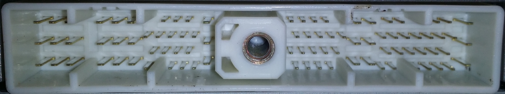
Click for larger
Pin count: 86: ( Left to right, & top to bottom: 9; block of flat, 9; block of flat, 3; row of square, 5; row of square, 4; row of square, 3; row of square, 3; column of flat, 4; row of square, 5; row of square, 5; row of square, 4; row of square, 6; block of flat, 4; row of square, 7; row of square, 6; row of square, 6; row of square, 3; column of flat )
Ascii Pin Layout Diagram
'X'= Frame, 'O'=Pin: Wide & Flat, 'i'=Pin Narrow & Square; '.' to avoid `html tidy` squashing spaces.XXXXXXXXXXXXXXXXXXXXXXXXXXXXXXXXXXXXXXXXXXXXXXXXXXXXXXXXXXXXXXXXXXXXXXXX XX....................i.i.i.....XXX.i.i.i.i...........i.i.....i.i.....XX XX.O.O.O...O.O.O..............O.XXX.............O.O.................O.XX XX.................i.i.i.i.i....XXX..i.i.i.i.i.......i.i.i.i.i.i.i....XX XX.O.O.O...O.O.O..............O.XXX.............O.O.................O.XX XX..................i.i.i.i.....XXX.i.i.i.i.i.........i.i.i.i.i.i.....XX XX.O.O.O...O.O.O..............O.XXX.............O.O.................O.XX XX.....................i.i.i....XXX..i.i.i.i.........i.i...i.i.i.i....XX XXXXXXXXXXXXXXXXXXXXXXXXXXXXXXXXXXXXXXXXXXXXXXXXXXXXXXXXXXXXXXXXXXXXXXXX
Pin-out; Page=1574 of 1998.pdf B84 2-7 [T10BI0] Footer=286. Frame grab of 96 pin connector diagram:
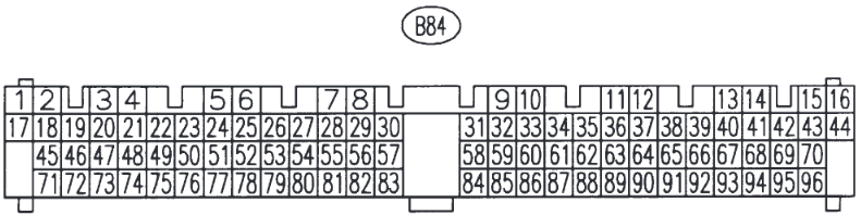
Older Pages=2858_62M_1997_BD-BG-BK
(Partial diagram of B84, Just for "MASS AIR FLOW SENSOR CIRCUIT LOW INPUT" but it is same as 1998 pdf, no columns of pins out of alignement, unlike mine (jhs@)).
ECM Removal Page=283 of Pages=2858_62M_1997_BD-BG-BK Footer=32
Newer Pages=3071 of 1999 BD-BG-BK
Partial Pinout; Page=1459 of Pages=3071_69M_1999_BD-BG-BK B84 2-7 [T10B0] Footer=148
(Partial diagram of B84, Just for "B. STARTER MOTOR CIRCUIT" but it is same as 1998 pdf, no columns of pins out of alignement, unlike mine (jhs@)).
Australian Pages=4442_121M_liberty_1998_2003.pdf
Page=422 Footer=EN(H4SO)-24
ENGINE (DIAGNOSTICS)
5. Engine Control Module (ECM) I/O Signal
A: ELECTRICAL SPECIFICATION
Page=838 Footer=EN(H4SOw/oOBD)-18
ECM (ECU Engine Control Module / Unit / Computer) Label On Top
Printed: 18
Printed: 22644 AA630 NUMBER MANUFACTURER - ERSATZTEILHERSTELLERNUMMER
Printed: A56-000 R40 NUMBER PARTS - TEILENUMMER
Engraved: See ~/txt/car/2legacy_trend/undated/notes.rof
Printed: UNISIA JECS CORPORATION
Printed: MADE IN JAPAN
ECM (ECU Engine Control Module / Unit / Computer) Label on side:
02978252-WA56000R40WWW
Back To Index
ECM (ECU Engine Control Module / Unit / Computer) Suppliers (found while searching for pin out numberings)
Awful crap English, presumably a translation from what language ? it makes little sense
auto24parts . com / de_DE / p / MOTORSTEUERGERAT - ECU - STEUERGERAT - SUBARU - 22644 - AA630 % 2C - 22644AA630 % 2C - A56 - 000 - R40 % 2C - A56000R40 -/ 44135
Horribly dense German, I got exasperated reading & gave up. Is it a bad translation from eg Japanese ? or just a horribly written original, by a German ?
OPTION AVAILABLE: Plug & Play / Locked / Ready for programming USED ORIGINAL IN GOOD CONDITION Variant: Locked Euro 125 Euro
Variant: Unlocked ready for programming Euro 225 Euro
MOTORSTEUERGERAET ECU ENGINE CONTROLLER SUBARU 22644 AA630, 22644AA630, A56-000 R40, A56000R40
Back To Index
Odds
- STH=?
- Search for "SUBARU SELECT
MONITOR"
Shows various test devices on sale on ebay & a mouse zoom in on connectors may be instructive. - thehill . com / policy / transportation / 4560949 - subaru - recalls - over - 118000 - vehicles - over - airbag - issue /
- www . nhtsa . gov / vehicle - safety / takata - recall - spotlight 2024-03-27 : Subaru recalls over 118, 000 vehicles over airbag issue 2020-2022 Outback and Legacy
- en . wikipedia . org / wiki / National _ Highway _ Traffic _ Safety _ Administration
- Acronyms: TCS = Traction Control System (I
guess)
Some others at: en . wikipedia . org / wiki / Electronic_stability_control - ultimatesubaru . org / forum / topic / 167667 - factory - service - manual/
- jdmfsm.info/Auto/Japan/Subaru/--Old%20Models--/ Not much there
- ABS = Anti-lock braking system
-
Search
- Web Search Engines
- Some Android PDF viewer apps, eg Hancom, support a text string search function
-
Pictures: Whole Directory & Pictures: Index
- en . wikipedia . org / wiki / CAN_bus
-
en
. wikipedia . org / wiki / Engine_control_unit
-
en . wikipedia .
org / wiki / JECS
http://ecupro.eu/29-modul-subaru-hitachiunisia-jecs-mmc-flash ref to info@ecupro.ru - Back To Index
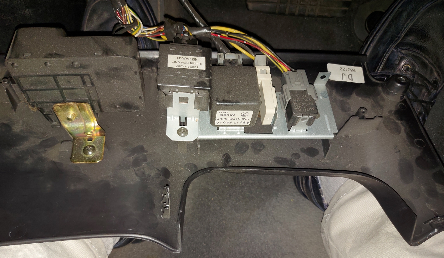
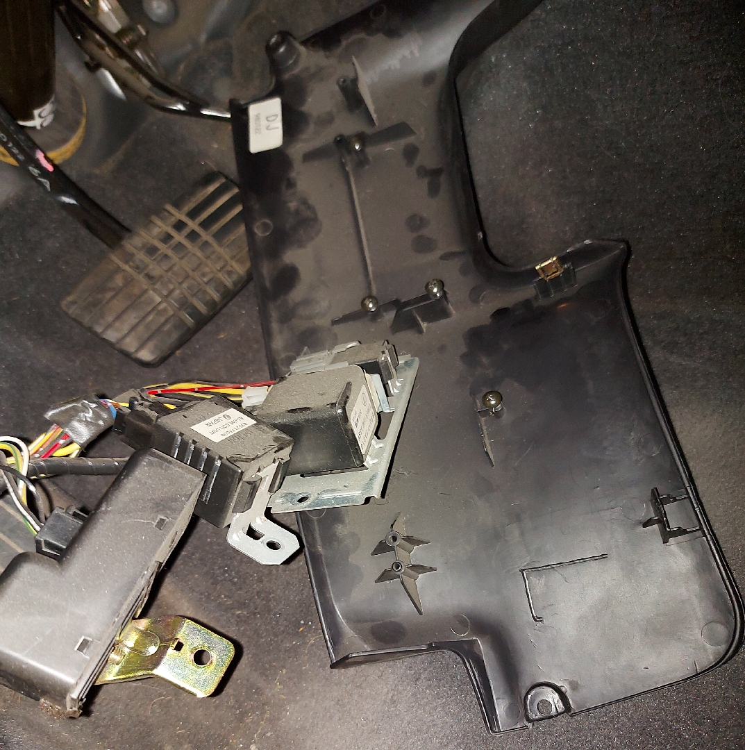
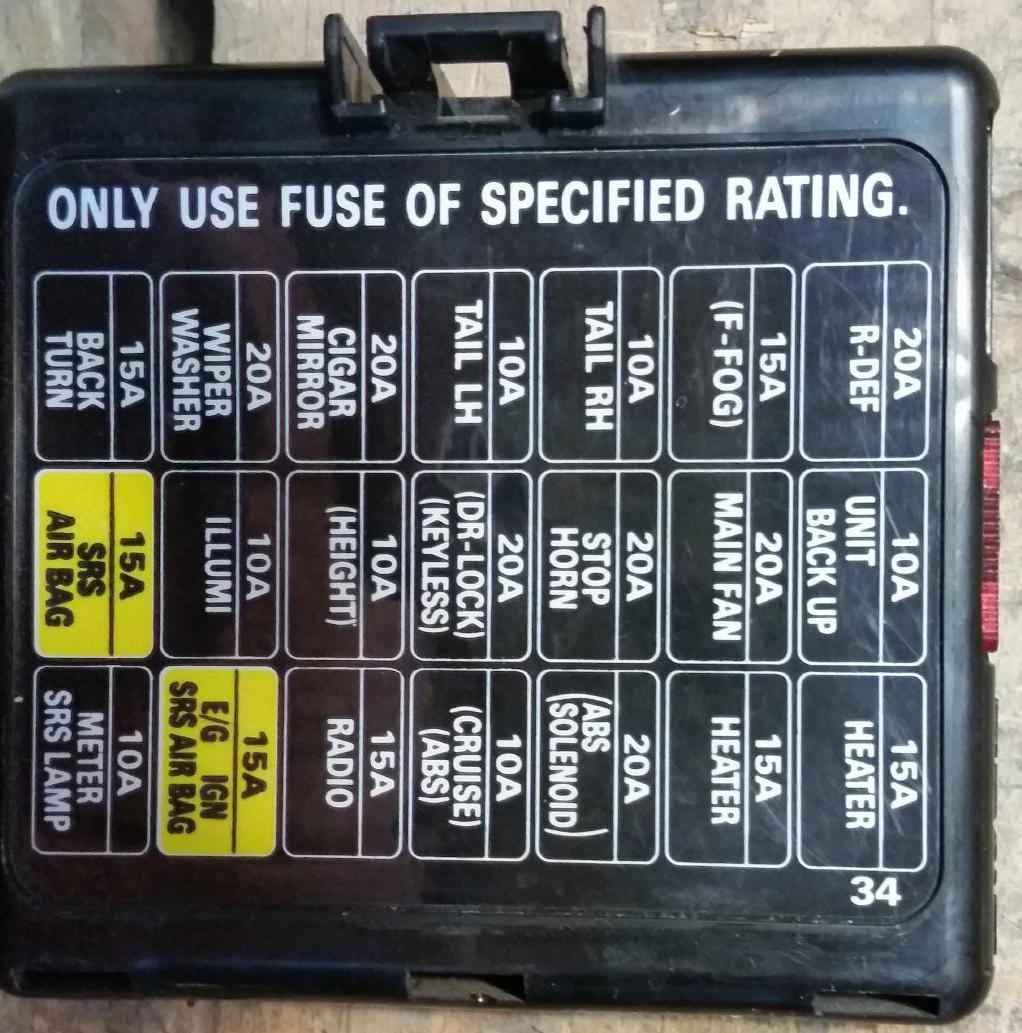
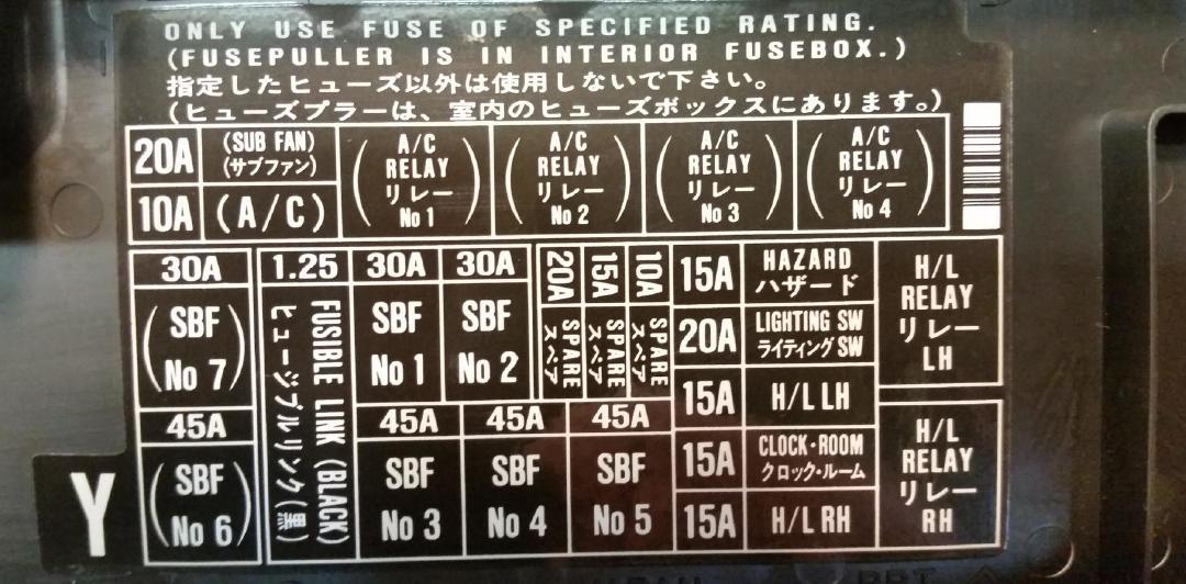
Fuses: Covers, Numbers, Ratings, Functions
| Internal fuses, cover mounted
vertical by left knee of driver in LHD car (click photo for larger): |
External fuses, cover mounted
horizontal, seen from left wing of LHD car (click photo for larger): |
|||||||||||||||||||||||||||||||||||||||||||||||||||||||||||||||||||||||||||||
 |
 |
|||||||||||||||||||||||||||||||||||||||||||||||||||||||||||||||||||||||||||||
|
Back To Index
Manuals Whole: List & Detail
Manuals List
-
workshop - manuals . com / subaruownersmanual . pdf
Owners (=Users/ Drivers) Manual, NOT A WORKSHOP / SERVICE MANUAL, Pages=379 -
Pages=2461_62M_jhsm.pdf, Singular Large Pdf from jhs
-
A Combined Repair Merge of myriad
purchased mini .pdf in .zips
Chapters in table below - I currently am instead using Pages=2436_86M_1998.pdf guessing that might (or not) be better ordering ?
-
A Combined Repair Merge of myriad
purchased mini .pdf in .zips
-
Pages=2436_86M_1998.pdf Singular Large PDF from mega.nz & sl-i.net
Downloaded 2024-03-26, Written 2019-12-06, probably for USA model
More Detail -
Other USDM examples ( in usdm/ & usdm.LN/ ) pre & post Pages=2436_86M_1998.pdf,
See Also: usdm
Pre: As Pages=2436_86M_1998.pdf, (content indexed above) says "Please study and then utilize this supplement together with LEGACY SERVICE MANUAL and SERVICE MANUAL SUPPLEMENTS published already."
Post: As 1999 might have manual corrections that are applicable to My (jhs@) 1998 car
Downloaded from URLS tabulated at
sl - i . net / FORUM / showthread . php ? 18087 - Subaru - Factory - Service - Manuals -( FSM )- Every - Model - USDM - EU &s=b87f017a605c4ca4f829efb2a1b946f9
Stored here locally-
Pages=1995_53M_1995_BD-BG-BK
(repeat of "1995" is just
coincidence)
mega . nz / file / AIZgTJ4L # e8ROkuOyGRPJ4V4wl_0P9MC3Jpdb2nlRuQ8aFzVF8AM
usdm_legacy_fsm_1995_pdf_msa5tcd95l__open-bracket_bd-bg-bk_close-bracket_.pdf
"1995 LEGACY SERVICE MANUAL,
QUICK REFERENCE INDEX,
REPAIR SECTION"
FOREWORD
-
Pages=2453_58M_1996_BD-BG-BK
mega . nz / file / BcByDJBQ # j-76K5N14oZ7KsHBtDFG0150qvxCfClHBJJ1rRwSp5c
usdm_legacy_fsm_1996_pdf_msa5tcd96l__open-bracket_bd-bg-bk_close-bracket_.pdf
"1996 LEGACY SERVICE MANUAL,
QUICK REFERENCE INDEX,
REPAIR SECTION"
FOREWORD
-
Pages=2858_62M_1997_BD-BG-BK
mega . nz / file / IQByTZoD # VV5Essvgh9nU_CAtzJZ6Kwe_qrwoyknQNEZno2yZijY
usdm_legacy_fsm_1997_pdf_msa5tcd97l__open-bracket_bd-bg-bk_close-bracket_.pdf
"1997 LEGACY SERVICE MANUAL,
QUICK REFERENCE INDEX,
REPAIR SECTION" FOREWORD
-
Pages=2436_86M_1998_BD-BG-BK
mega . nz / file / cMZiQBSQ # 22oGQRVNqexypE_PPggb5VhrfwqTDM_coRKTyjiDeVM
usdm_legacy_fsm_1998_pdf_msa5tcd98l__open-bracket_bd-bg-bk_close-bracket_.pdf
"1998 LEGACY SERVICE MANUAL SUPPLEMENT,
QUICK REFERENCE INDEX,
GENERAL INFORMATION SECTION" FOREWORD
The first one that in Foreword also has:The star marks for referred title indexes represent :I guess MY means Manufacturing Year as that acronym is in also used in en . wikipedia . org / wiki / On- board_diagnostics.
*1: Refer to 95MY Service Manual .
*2: Refer to 96MY Service Manual Supplement.
*3: Refer to 95MY Right Hand Drive Service Manual Supplement.
*4: Refer to 96MY Right Hand Drive Service Manual Supplement.
*5: Refer to 96MY Service Manual Supplement ABS 5.3 equipped model .
*6: Refer to 96MY Service Manual Supplement enhanced evaporative emission control system equipped model.
*7: Refer to 96MY Service Manual Supplement right hand drive vehicle enhanced evaporative emission control system equipped model.
*8: Refer to 97MY Service Manual Supplement.
*9: Refer to 97MY Service Manual Supplement for SUS model .
*10: Refer to 97MY Service Manual Supplement for ABS 5.3i equipped model .
*11: Refer to 97MY Service Manual Supplement for rear window defogger timer equipment model .
*12: Refer to 98MY Service Manual Supplement. -
Pages=3071_69M_1999_BD-BG-BK
mega . nz / file / 9ZBEWBLZ # i-31aaQ8-5dUqGlhMI81BOeN3LhyCj5ekGgKH1v0Cvk usdm _ legacy _ fsm _ 1999 _ pdf _ msa5tcd99l _ _ open-bracket _ bd-bg-bk _ close-bracket _.pdf
The 2nd that also has in Foreword:
"1999 LEGACY SERVICE MANUAL SUPPLEMENT, QUICK REFERENCE INDEX, GENERAL INFORMATION SECTION" FOREWORDThe star marks for referred title indexes represent :
*1: Refer to 95MY Service Manual .
*2: Refer to 96MY Service Manual Supplement.
*3: Refer to 95MY Right Hand Drive Service Manual Supplement.
*4: Refer to 96MY Right Hand Drive Service Manual Supplement.
*5: Refer to 96MY Service Manual Supplement ABS 5.3 equipped model.
*6: Refer to 96MY Service Manual Supplement enhanced evaporative emission control system equipped model.
*7: Refer to 96MY Service Manual Supplement right hand drive vehicle enhanced evaporative emission control system equipped model.
*8: Refer to 97MY Service Manual Supplement.
*9: Refer to 97MY Service Manual Supplement for SUS model.
X10: Refer to 97MY Service Manual Supplement for ABS 5.3i equipped model.
X11: Refer to 97MY Service Manual Supplement for rear window defogger timer equipment model.
X12: Refer to 98MY Service Manual Supplement.
X13: Refer to 99MY Service Manual Supplement for SUS precedence production vehicle .
X14: Refer to 99MY Service Manual Supplement - Back To Index
Pages=4442_121M_Liberty_1998_2003.pdf, SINGULAR LARGE PDF, Australian
-
Pages=1995_53M_1995_BD-BG-BK
(repeat of "1995" is just
coincidence)
Manuals Detail
Pages=2436_86M_1998.pdf Singular Large
PDF from mega.nz & sl-i.net
Downloaded 2024-03-26, Written 2019-12-06, probably for
USA model
- See Also: usdm-other
- There are a few pages missing from this one, that I have in Pages=2461_62M_jhsm.pdf
-
The rest of this list is Not an index of this file, but
just notes pertinent to My
(jhs@) current job.
----------------------- -
Page=1 of Pages=2436_86M_1998.pdf,
Footer={Deduced:1},
1998 LEGACY SERVICE MANUAL SUPPLEMENT QUICK REFERENCE INDEX, GENERAL INFORMATION SECTION, FOREWORD
"Please study and then utilize this supplement together with LEGACY SERVICE MANUAL and SERVICE MANUAL SUPPLEMENTS published already." -
Page=93 of Pages=2436_86M_1998.pdf,
Footer={Deduced:1},
1998 LEGACY SERVICE MANUAL, QUICK REFERENCE INDEX, REPAIR SECTION, FOREWORD - Page=1200 of Pages=2436_86M_1998.pdf, Footer={Deduced:1}, Section=6-2 BODY ELECTRICAL SYSTEM
-
Page=1289 of Pages=2436_86M_1998.pdf,
Footer={Deduced:1}, Section=2-7 ON-BOARD DIAGNOSTICS II
SYSTEM
- T DIAGNOSTICS 2
- 1. General 2
- 2. Electrical Components Location 3
- 3. Diagnosis System 44
- 4. Cautions 62
- 5. Specified Data 64
- 6. Basic Diagnostic Procedure 70
- 7. Diagnostics for CHECK ENGINE Malfunction Indicator Lamp (MIL) 74
- 8. Diagnostics for Engine Starting Failure 87
- 9. General Diagnostic Table 114
- 10. Diagnostic Chart with Trouble Code for LHD Vehicles 116
- 11. Diagnostic Chart with Trouble Code for RHD Vehicles 420
-
Page=1314 of Pages=2436_86M_1998.pdf, Footer=26,
Section=Section=2-7_[T2C1]
Diagram of car with connectors hanging under dashboard
"Test mode connector" (single wire to spade clip wire), & "Data Link Connector" -
Page=1332 of Pages=2436_86M_1998.pdf, Footer=44,
Section=2-7_[T3A1]
3. Diagnosis System A: CHECK ENGINE MALFUNCTION INDICATOR LAMP (MIL) 1. ACTIVATION OF CHECK ENGINE MALFUNCTION INDICATOR LAMP (MIL) -
Page=1333 of Pages=2436_86M_1998.pdf, Footer=45,
Section=2-7_[T3B2]
"For details concerning diagnostic trouble codes, refer to <Ref. to Section=2-7_[T10A0]>"
jhs@: These are OBD-II codes, not flash codes -
Page=1335 of Pages=2436_86M_1998.pdf, Footer=47,
Section=2-7_[T3C1]
HOW TO USE SUBARU SELECT MONITOR - Page=1336 of Pages=2436_86M_1998.pdf, Footer=48,
Section=2-7_[T3C2]
Ref. to Data Link_Connector (where they show OBD) - Page=1346 of Pages=2436_86M_1998.pdf, Footer=58,
Section=2-7_[T3E2]
Re. jacking up front wheels to do a test: "Connect test mode connector" (they show 2 single spade connectors, looks T shape, next to probably U-shape) - Page=1347 of Pages=2436_86M_1998.pdf, Footer=58,
Section=2-7_[T3E3]
"After performing diagnostics and clearing the memory, check for any remaining unresolved trouble data: 1) Connect test mode connector ... connect the OBD-II general scan tool ... start the engine." - Page=1353 of Pages=2436_86M_1998.pdf,
Section=2-7_[T5A0], Footer=65,
5. Specified Data A: ENGINE CONTROL MODULE (ECM) I/O SIGNAL
"Content"="Test mode connector", "Connector: No."="B84", "Terminal No."="84", "Ignition SW ON (Engine OFF) "="5 ", "Engine ON (Idling)"="5", "Note"="When connected: 0" - Page=1357 of Pages=2436_86M_1998.pdf, Footer=69,
Section=2-7_[T5C0]
Data link signal (Subaru select monitor) Connector No, B56, Terminal No. 12 & 13 -
Page=1358 of Pages=2436_86M_1998.pdf, Footer=70,
Section=2-7_[T6A1]
... 3) Perform the clear memory mode. <Ref. to Section=2-7_[T3D0]>
Re. Section=2-7_[T3D0] :- Pages=2436_86M_1998.pdf, Has no Section=2-7_[T3D0]
- Page=1344 of Pages=2436_86M_1998.pdf, has Section=2-7_[T3D1]
- There is no Section=2-7_[T3D0] in Pages=2461_62M_jhsm.pdf,
Footer=55, between { Page=341 Section=2-7_[T3C9]
& Page=342 Footer=56, Section=2-7_[T3D1] }
- Page=1418 of Pages=2436_86M_1998.pdf,
Section=2-7_[T10E5] 10E6 : CHECK PRESSURE SOURCES SWITCHING SOLENOID VALVE. 1) Turn ignition switch to OFF. 2) Connect Test mode connector. - Page=1428 of Pages=2436_86M_1998.pdf,
Section=2-7_[T10H0]
Another ref. to non existent Section=2-7_[T3D0], a ref. to Section=2-7_[T3E0] - Page=1545 of Pages=2436_86M_1998.pdf,
Section=2-7_[T10BA4] 10BA2 : CHECK GROUND CIRCUIT OF
COMBINATION METER.
Pull out combination meter from instrument panel. (jhs@: = dash board) <Ref. to Section=6-2_[W14A1] (Page=1226 of Pages=2436_86M_1998.pdf)> - ECM (ECU Engine
Control Module / Unit / Computer) (B84) to OBD (B40) Pin
Outs and Circuit Diagram
Page=1574 of Pages=2436_86M_1998.pdf,
Section=2-7_[T10BI0]
"SERIAL COMMUNICATION LINK MALFUNCTION"
"After repair or replacement of faulty parts, conduct CLEAR MEMORY and INSPECTION MODES.
<Ref. to Section=2-7_[T3D0]> and <Ref. to Section=2-7_[T3E0]>"
Pin Out of ECM (ECU Engine Control Module / Unit / Computer) Connector B84 & Cabling between ECM (ECU Engine Control Module / Unit / Computer) Connector B84 Pin 93 & Subaru Pin 10 on Plug B40 OBD-II Data Link_Connector OBD-II (Labeled: "To Subaru select monitor & OBD-II general scan tool") - Page=1575 of Pages=2436_86M_1998.pdf, Footer=287,
Section=2-7_[T10BI2]
Shows a test between ECM (ECU Engine Control Module / Unit / Computer) B84 Pin 93 ECM (ECU Engine Control Module / Unit / Computer) (B84) to OBD (B40) Pin Outs and Circuit Diagram & B40 OBD-II From Subaru Manual Pin=10 = Wiki Pin=7 = K-Line
I don''t have an OBD-II yet, but maybe the cable is in place from ECM (ECU Engine Control Module / Unit / Computer) to where ? - Page=1695 of Pages=2436_86M_1998.pdf, Footer=407,
Section=2-7_[T10DA3]
: CHECK HARNESS BETWEEN ECM AND COMBINATION METER CONNECTOR. - Page=1769 of Pages=2436_86M_1998.pdf,
Section=2-7_[T11AZ4] CHECK GROUND CIRCUIT OF COMBINATION METER Pull out combination meter from instrument panel. (jhs@: = dash board) <Ref. to Section=6-2_[W14A1] (Page=1226 of Pages=2436_86M_1998.pdf), > - Page=1775 of Pages=2436_86M_1998.pdf, Footer=487,
Section=2-7_[T11BA3]
11BA2 : CHECK GROUND CIRCUIT OF COMBINATION METER. &
11BA3 : CHECK INPUT SIGNAL FOR ECM. - Page=1827 of Pages=2436_86M_1998.pdf, Footer=539,
Section=2-7_[T11CS3]
11CS3 : CHECK DRAIN VALVE OPERATION 1) Turn ignition switch to OFF 2) "Connect Test mode connector" 3) Turn ignition switch to ON. - Page=1835 of Pages=2436_86M_1998.pdf,
Footer=(Deduced 1), Section=3-2
AUTOMATIC TRANSMISSION AND DIFFERENTIAL .. T DIAGNOSTICS .. 1. Supplemental Restraint System "Airbag"...
Merely a warning cables run nearby. - Page=1974 of Pages=2436_86M_1998.pdf, Footer=140, Section=end of Section=3-2 AUTOMATIC TRANSMISSION AND DIFFERENTIAL
- Page=1975 of Pages=2436_86M_1998.pdf,
Footer=(Deduced) 1, Section=4-4 BRAKES
1976 another warning about air Bag yellow cable proximity -
jhs: Clear by Pin 6
method.
- Page=1989 of Pages=2436_86M_1998.pdf,
Footer=15, Section=4-4_[T6D1]
BRAKES 6. Diagnostics Chart for On-board Diagnosis System
1. CALLING UP A TROUBLE CODE
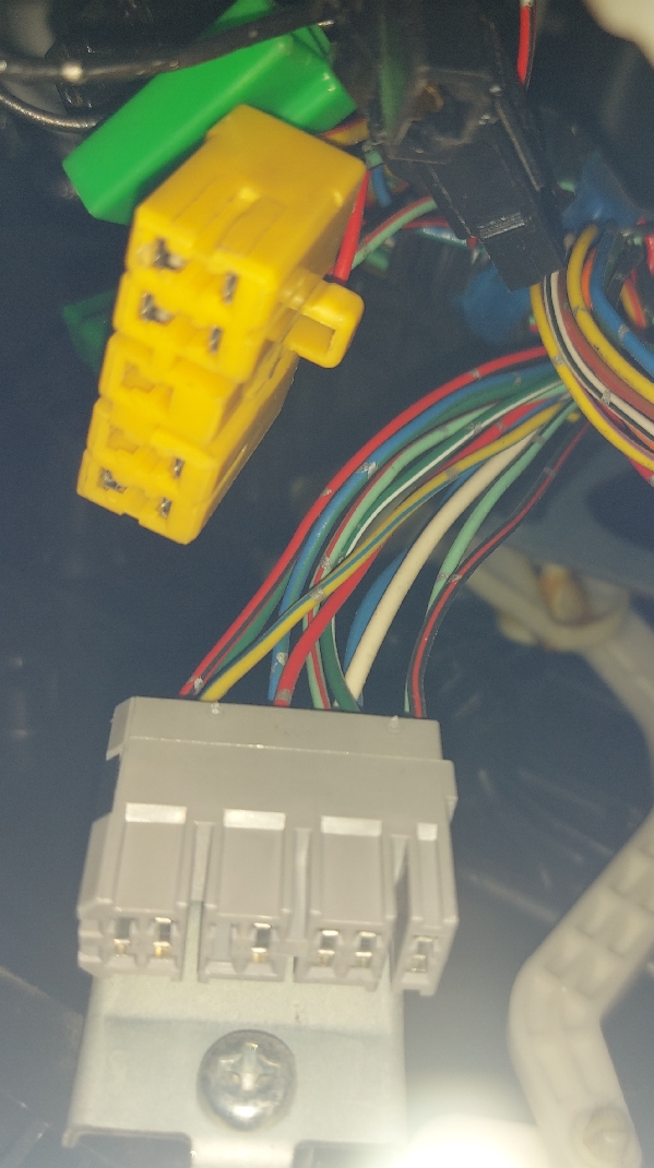
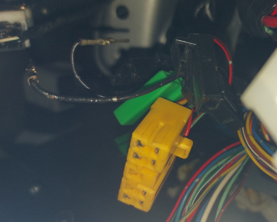
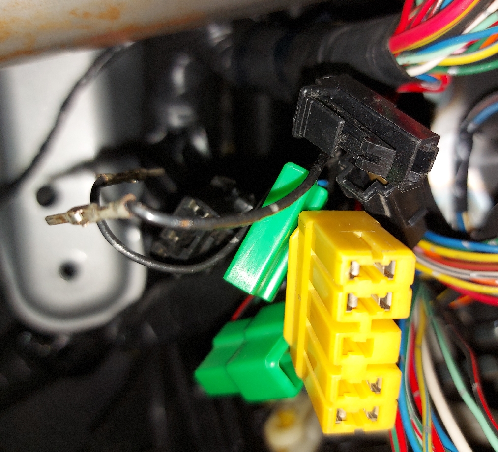
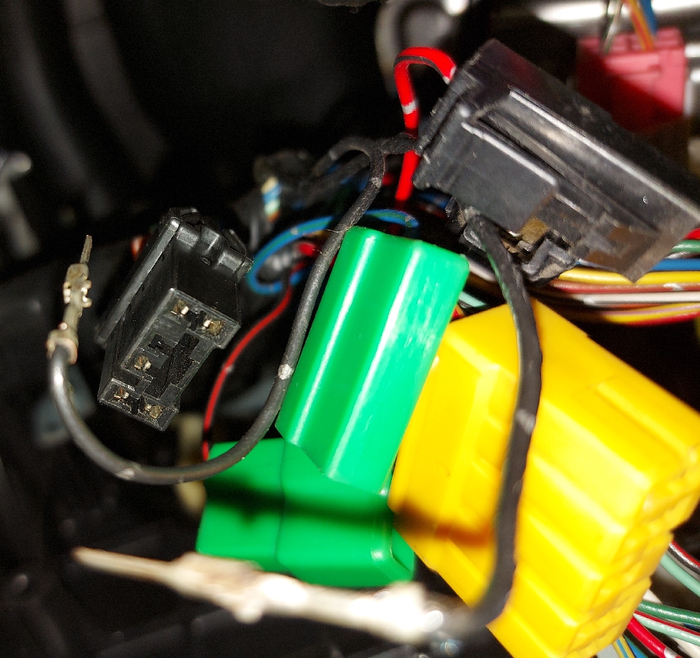
1) "Take out diagnosis connector (Which?) from side of driver''s seat heater unit" Huh ? Weird !
Diagram B4M0082D shows what looks similar to, the U-shaped connector with labels "3 terminal" on lower left & "6 terminal" on lower right, and also 2 loose pins labeled as "Diagnosis terminals".
"Ignition switch OFF. Connect Diagnosis Connector terminal 6 to diagnosis terminal. Turn ignition switch ON." - Page=1990 of Pages=2436_86M_1998.pdf,
Footer=16, Section=4-4_[T6D2]
BRAKES 6. Diagnostics Chart for On-board Diagnosis System
2. CLEARING MEMORY
" 1) After calling up a trouble code, disconnect diagnosis connector terminal 6 from diagnosis terminal.
2) Repeat 3 times within approx. 12 seconds; connecting and disconnecting terminal 6 and diagnosis terminal for at least 0.2 seconds each time."
- Page=1989 of Pages=2436_86M_1998.pdf,
Footer=15, Section=4-4_[T6D1]
- Page=1997 of Pages=2436_86M_1998.pdf, Footer=23,
Section=4-4_[T7B4] BRAKES,
7. Diagnostics Chart for ABS Warning Light Circuit and Diagnosis Circuit Failure,
7B2 : CHECK DIAGNOSIS TERMINAL.
"Measure resistance between diagnosis terminals (B81) and chassis ground" "Is the resistance less than 0.5 # ?"
Check continuity to ground. - Page=2001 of Pages=2436_86M_1998.pdf,
Section=4-4_[T7C1] BRAKES 7. Diagnostics Chart for ABS Warning Light Circuit and Diagnosis Circuit Failure
Shows 2 x B81 "Diagnosis Terminal" pins (adjacent to & that could go in Pin 6 of U-shape Diagnosis Connector B82),
B82 is clearly shown as U-shape connector Pin 6 goes to Pin 19 of F2=B100 (20 pins), & further on to pin 4 of "ABS control module and hydraulic control unit". - Page=2141 & 2142 of Pages=2436_86M_1998.pdf, Footer=2,
Section=5-5 SUPPLEMENTAL RESTRAINT SYSTEM,
Section=5-5_[T100] SUPPLEMENTAL RESTRAINT SYSTEM
1. Electrical Components Location - Page=2143 of Pages=2436_86M_1998.pdf, Footer=3,
Section=5-5_[T200]
SUPPLEMENTAL RESTRAINT SYSTEM 2. Schematic
Combination meter: Pin 18 to Airbag warning light. Fed from Pin 1 of 7pin U B31 & AB1 - Page=2150 of Pages=2436_86M_1998.pdf,
5-5_[T4A1]
SUPPLEMENTAL RESTRAINT SYSTEM 4. Diagnostics Chart for On-board Diagnostic System
Repair and replace. <Ref. to Section=5-5_[T4D0]>
Perform ON-BOARD DIAGNOSTICS. <Ref. to Section=5-5_[T4B0]>
Does trouble code indicate? <Ref. to Section=5-5_[T5A0]>
Repair and replace. <Ref. to Section=5-5_[T5AA0]> Go to step 4A3.
Repair and replace. <Ref. to Section=5-5_[T4D0]>
4A4 Perform clear memory. <Ref. to Section=5-5_[T4C0]>
1) Turn ignition switch ON (with engine OFF). 2) Connect DIAG. terminal (A) to No. 1 terminal of Diagnosis Connector (B) 4) Turn the ignition switch "OFF" and remove the DIAG. terminal from No.1 terminal of diagnosis connector (Which?). - Page=2151 of Pages=2436_86M_1998.pdf, Footer=11,
Section=5-5_[T4D3]
C: CLEAR MEMORY
one DIAG. terminal "A" (A) on diagnosis connector (Which?) (C) terminal No. 1. While warning light is flashing, connect the other DIAG. terminal "B" (B) on terminal No. 2 for at least three seconds.
4D1 : CHECK TROUBLE CODE INDICATES. Are trouble codes 4, 12, 13, 22, 34, 41, 42, or 43 indicated? <Ref. to Section=5-5_[T5A2]>
(My trouble codes: 11, 22, 12)
Go to step 4D2.
4D2 : CHECK TROUBLE CODE INDICATES. Are trouble codes 4, 22, 34, 42 indicated? <Ref. to Section=5-5_[T5A2]> Go to step 4D3. - Page=2155 of Pages=2436_86M_1998.pdf,
Section=5-5_[T5A1] SUPPLEMENTAL RESTRAINT SYSTEM 5. Diagnostics Chart with Trouble Code A: TROUBLE CODES 1. LIST OF TROUBLE CODES
(My trouble codes: 11, 22, 12) - Page=2169 of
Pages=2436_86M_1998.pdf,
Section=5-5_[T5G1] SUPPLEMENTAL RESTRAINT SYSTEM 5. Diagnostics Chart with Trouble Code 5F5 : FUSE NO. 8 (IN JOINT BOX) INSPECTION
Looks like Fuse box has 7 columns, x 3 height = 21, so I guess layout is as shown at Fuse Covers. : Page=2192 of Pages=2436_86M_1998.pdf, shows #15 is bottom left - Page=2174 of Pages=2436_86M_1998.pdf,
Section=5-5_[T5L0] SUPPLEMENTAL RESTRAINT SYSTEM
5. Diagnostics Chart with Trouble Code
M: TROUBLE CODE 22
- Page=2189 of Pages=2436_86M_1998.pdf,
Section=5-5_[T5Y2] SUPPLEMENTAL RESTRAINT SYSTEM 5. Diagnostics Chart with Trouble Code Y: AIRBAG WARNING LIGHT REMAINS ON.
... Grounding circuit is fault ... - Page=2190 of Pages=2436_86M_1998.pdf,
Section=5-5_[T5Y3] SUPPLEMENTAL RESTRAINT SYSTEM 5. Diagnostics Chart with Trouble Code
Diag. show Airbag warning light module - Page=2193 of Pages=2436_86M_1998.pdf,
Connectors (AB3) and (AB8) below steering column. - Page=2247 of Pages=2436_86M_1998.pdf, Footer=11,
Section=6-2b_[T3A3]
BODY ELECTRICAL SYSTEM (ELECTRICAL PARTS) 3. Combination Meter
... Speedo ... "Is the voltage less than 10 [ohm symbol] ?" !!?? - Page=2279 of Pages=2436_86M_1998.pdf,
1998 LEGACY SERVICE MANUAL QUICK REFERENCE INDEX
WIRING DIAGRAM SECTION
FOREWORD - Page=2282 of Pages=2436_86M_1998.pdf,
Section=6-3_[D1A0] WIRING DIAGRAM
1. General Description
A: WIRING DIAGRAM
Pin numbering convention.
(Where one can see how Subaru placed an OBD wrong way up, then got the Data Link_Connector (OBD) pin layout wrong.) - Page=2290 of Pages=2436_86M_1998.pdf, Footer=10,
Section=6-3_[D400] WIRING DIAGRAM
4. How to Use Wiring Diagram - Page=2290 of Pages=2436_86M_1998.pdf, Footer=?, Section=6-3_[D400] WIRING DIAGRAM 4. How to Use Wiring Diagram
- Page=2294 of Pages=2436_86M_1998.pdf, Footer=?, Section=6-3_[D6A1] WIRING DIAGRAM, 6. Wiring Diagram, A: POWER SUPPLY ROUTING, 1. LHD MODEL
- Page=2302 of Pages=2436_86M_1998.pdf, Footer=?, Section=6-3_[D6B1] WIRING DIAGRAM B: GROUND DISTRIBUTION 1. LHD MODEL
- Page=2304 of Pages=2436_86M_1998.pdf, Footer=?,
Section=6-3_[D6B1] WIRING DIAGRAM,
Pin-outs of lots of connectors - Page=2303 of Pages=2436_86M_1998.pdf,
Footer=23,
SRS Harness B31 - Page=2304 of Pages=2436_86M_1998.pdf,
Footer=??,
B40 OBD Sub. pins 12 & 13 (= wiki pins 5 & 4 ) = Ground = Connected to loads of other connectors inc. Pin 9 on B78 Yellow 9 pin Data Link Connector. - Page=2306 of Pages=2436_86M_1998.pdf,
Footer=26,
Section=6-3_[D6B2] 2. RHD MODEL -
Page=2309 of Pages=2436_86M_1998.pdf, Footer=29,
Section=6-3_[D6C0],
C: AIRBAG SYSTEM
Connectors inc.- B79 Check Connector 5 wires up to Pin#8
- Pins 1 & 2 of 6 pin U-shaped B82 Diagnosis Connector
-
Page=2313 of Pages=2436_86M_1998.pdf,
Section=6-3_[D6E0] 6. Wiring Diagram
Connectors:- B40 OBD-II connector socket Sub Pin 4 & 5 = Select Monitor In & Out
- Diagnosis Connector B82 6 Pin U-shape
- Page=2324 of Pages=2436_86M_1998.pdf,
Section=6-3_[D6J0] 6. Wiring Diagram J: COMBINATION METER - Page=2331 of Pages=2436_86M_1998.pdf,
Footer=51,
Section=6-3_[D6M1] 6. Wiring Diagram
OBD-II connector socket service connector Subaru Pin 10 K-Line to ECM (ECU Engine Control Module / Unit / Computer) Connector B84 Pin 93 ECM (ECU Engine Control Module / Unit / Computer) (B84) to OBD (B40) Pin Outs and Circuit Diagram Colour=OrW (From Section=6-3_[D1A0] (Pages=2436_86M_1998.pdf), is Orange base White strip ).
Doesn''t seem to be connected to anything else Need to do a scan of OCR file. JJLATER - Page=2334 of Pages=2436_86M_1998.pdf, Footer=54,
Section=6-3_[D6M2]
Show 5 wires to 14 pins of Check Connector B79 colour=Gray.
Firefox while displaying this page shows in tab title: "June 28 1991, Tweddl - usdm" -
Page=2335 of Pages=2436_86M_1998.pdf, Footer=55,
Section=6-3_[D6M2]
B78 yellow 9 pins & B40 OBD-II connector socket (where Sub_pin_10 (K-Line) connects to Engine Control Module Pin=93, Orange+White wire )
How to connect an OBD2 to B78 Data Link Connector:- Sub Pin 12 & Sub Pin 13 : to B78 Data Link Connector Pin 9
- Sub Pin 1 : to +12 V
- Sub Pin 10 : ECM (ECU Engine Control Module / Unit / Computer) Connector B84 Pin 93ECM (ECU Engine Control Module / Unit / Computer) (B84) to OBD (B40) Pin Outs and Circuit Diagram Colour=OrW (From Section=6-3_[D1A0] (Pages=2436_86M_1998.pdf), is Orange base White strip ),
- Sub Pin 4 : to B78 Data Link Connector Pin 2
- Sub Pin 5 : to B78 Data Link Connector Pin 3
- Page=2395 of Pages=2436_86M_1998.pdf,
Section=6-3_[D7A0]
7. Electrical Unit Location -
Page=2395 of Pages=2436_86M_1998.pdf,
Footer=115, Section=6-3_[D7A0]
7. Electrical Unit Location A: LIST A few samples:- Check Connector - 6-3_[D7B2]
- Data
Link_Connector (for OBD-II G.S.T.) Section=2-7_[T2A1], [T2B1],
[T2C1]
Data link connector (for S.S.M.) Section=2-7_[T2A1], [T2B1], [T2C1] - Diagnosis connector Section=4-4_[T300] diagnosis terminal (Ground) Section=4-4_[T300]
- Mode actuator - 6-3_[D7B2]
- M/B 6-3_[D7B1]
- Test mode connector - Section=2-7_[T2A1], [T2B1], [T2C1]
- Page=2397 of Pages=2436_86M_1998.pdf, Section=6-3_[D7B3] : (25) "Check Connector" location is far right edge of removable knee cover under dash board.
- Page=2403 of Pages=2436_86M_1998.pdf, Footer=123,
Section=6-3_[D8B1]
front wiring harness LHD - Page=2419 of Pages=2436_86M_1998.pdf, Footer=139,
Section=6-3_[D8F1]
Electrical Wiring Harness and Ground Point - -----------------------
-
Unexpected page ordering:
-
Page=331 of Pages=2436_86M_1998.pdf,
Footer={Deduced:1}, Section=2-7
FUEL INJECTION SYSTEM - Page=337 of Pages=2436_86M_1998.pdf, Footer=7, Section=2-7_[C300]
-
Page=338 of Pages=2436_86M_1998.pdf,
Footer=8, Section=2-7_[W1A0]
-
Page=339 of Pages=2436_86M_1998.pdf,
Footer=8, Section=2-7_[W2A0]
- Page=1333 of Pages=2436_86M_1998.pdf, Footer=45, Section=2-7_[T3B2] ON-BOARD DIAGNOSTICS II SYSTEM
-
Page=331 of Pages=2436_86M_1998.pdf,
Footer={Deduced:1}, Section=2-7
- "Diagnosis Connector" (6 Pin Black B82) 2 wires pins 1 & pin2 on 6 pin Connector
- Back To Index
Pages=4442_121M_Liberty_1998_2003.pdf, SINGULAR LARGE PDF - Australian name: Liberty
- Page=14 Footer=? & Page 16 Footer=? & Page=53 Footer=? : Error codes Clear Mem : Section=5-5_T4C0
- Page=107 : Engine Section 1: FU(H4SO)
-
Page=520 of 4442, Footers=EN(H4SO)-122
Engine section 1,
"After repair or replacement of faulty parts, conduct Clear Memory Mode
<Ref. to EN(H4SO)-47, OPERATION, Clear Memory Mode> and Inspection Mode
<Ref. to EN(H4SO)-40, OPERATION, Inspection Mode>." - Page=925 : Engine Section 2: FU(H6DO)
- Page=1543 : Engine Section 3: FU(H4DOSTC)
-
Page=1841 of 4442, Footers=EN(H4DOSTC)
ENGINE (DIAGNOSTICS)
-
Page=1875 of 4442, Footers=EN(H4DOSTC)-35
ENGINE (DIAGNOSTICS) - Clear Memory Mode
2.Clear Memory Mode
A: OPERATION
1. SUBARU SELECT MONITOR (NORMAL MODE) & 2. (OBD MODE)
Implicit refs to Data Link Connector (Normal Selector) & Data Link Connector (OBD) - Page=3571 Footer=AB-17 : Body Section : Airbag Control Module
- Page=3599 Footer=AB-15 : Body Section : Electrical Components Location
- Page=3606 Footer=AB-22 : Body Section : 9. Clear Memory Mode
- Page=3608 Footer=AB-24 : Body Section : 10.Airbag Warning Light Failure - AirBag Control Module AB6 Pinout 28 Pins
- Page=3812 Footer=IDI-2 : CHECK ENGINE & AIRBAG & AT OIL TEMP. warning light both 12V 1.4 W
- Page=3814 Footer=IDI-4 : COMBINATION METER SYSTEM: Luminescent meter has a CFL (Cold cathode fluorescent light) inverter that generates a high-tension current. Do not touch the inverter terminal when checking combination meter with ignition switch turned ON. (I think My (jhs@) older car probably does not have this)
- Page=3943 Footer=EI-35 : 16.Instrument Panel Assembly
- Page=4057 Footers=[WI 1] Wiring system Index
- Page=4108 Footer=WI-52 : AB6 AIRBAG CONTROL MODULE B31 Connector Yellow 12 pin
-
Page=4109 Footers=WI-53
"AIRBAG SYSTEM AIRBAG SYSTEM
6. Airbag System
A: SCHEMATIC
1. 4-CYLINDER NON-TURBO ENGINE MODEL"Air bag system (inc. belt pretensioners?)Sect 41 + 300 Seat Belts - Page=4182 Footer=WI-126 : 12.Combination Meter A: SCHEMATIC 1. 4-CYLINDER NON-TURBO ENGINE MODEL
- Page=4216 Footer=WI-160 : 15.Engine
Electrical System A: SCHEMATIC 1. LHD 4-CYLINDER ENGINE
WITHOUT OBD MODEL
ENGINE CONTROL MODULE with 28 + 25 pin connectors, 3 row, not like I have - Page=4390 Footer=WI-334 : 50.Front Wiring Harness
- Page=4422 Footer=WI-366 : 54.Instrument Panel Wiring Harness
Sample of sets of page number alignments between Manuals
Pages=2461_62M_jhsm.pdf,
Pages=2436_86M_1998.pdf,
Pages=4442_121M_liberty_1998_2003.pdf,
Manual Alignement Check Point Tags:
Back To Index
Building of My (jhs@) own merge of chapters
Pages=2461_62M_jhsm.pdf, My (jhs@) Own Singular Large Pdf -
A Combined Merge of myriad purchased mini .pdf in
.zips
Done by me, combining my ebayliverpool & emanualonline
Produced from script below:gs -dNOPAUSE -dBATCH -q -sDEVICE=pdfwrite -sOutputFile=\
Pages=2461_62M_jhsm.pdf,
\
diagnostics_section/foreword/all.pdf \
engine_section/emission_control_system_and_vacuum_fitting/all.pdf \
engine_section/on-car_services/all.pdf \
engine_section/engine__open-bracket_sohc_close-bracket_/all.pdf \
engine_section/engine__open-bracket_dohc_close-bracket_/all.pdf \
engine_section/engine_lubrication_system/all.pdf \
engine_section/engine_cooling_system/all.pdf \
diagnostics_section/engine_cooling_system/all.pdf \
diagnostics_section/on-board_diagnostics_ii_system/all.pdf \
engine_section/foreword/all.pdf \
engine_section/fuel_injection_system/all.pdf \
engine_section/fuel_system/all.pdf \
engine_section/exhaust_system/all.pdf \
engine_section/clutch/all.pdf \
engine_section/engine_and_transmission_mounting_system/all.pdf \
transmission_and_differential_section/manual_transmission_and_differential/all.pdf \
diagnostics_section/automatic_transmission_and_differential/all.pdf \
transmission_and_differential_section/automatic_transmission_and_differential/all.pdf \
transmission_and_differential_section/transmission_control_system/all.pdf \
transmission_and_differential_section/awd_system/all.pdf \
mechanical_components_section/suspension/all.pdf \
mechanical_components_section/wheels_and_axles/all.pdf \
mechanical_components_section/steering_system/all.pdf \
diagnostics_section/brakes/all.pdf \
mechanical_components_section/brakes/all.pdf \
mechanical_components_section/pedal_system_and_control_cables/all.pdf \
mechanical_components_section/heater_and_ventilator/all.pdf \
mechanical_components_section/air_conditioning_system/all.pdf \
body_section/body_and_exterior/all.pdf \
body_section/doors_and_windows/all.pdf \
body_section/seats,_seat_belts,_and_interior/all.pdf \
body_section/instrument_panel/all.pdf \
body_section/supplemental_restraint_system/all.pdf \
diagnostics_section/supplemental_restraint_system/all.pdf \
electrical_section/engine_electrical_system/all.pdf \
electrical_section/body_electrical_system/all.pdf \
diagnostics_section/body_electrical_system__open-bracket_cruise_control_close-bracket_/all.pdf \
diagnostics_section/body_electrical_system__open-bracket_electrical_parts_close-bracket_/all.pdf \
wiring_diagram/foreword/all.pdf \
wiring_diagram/wiring_diagram/all.pdf
Manual: Downloaded, Pages Merged To Chapters & Indexed
-
cd service_manual/ find .
-type f -name all\*.pdf | sort find . -type f -name
all\*.txt | sort
Chapter No. (eg Section=4-1), & Section No. (eg: [41A2])
Area: {General, Repair, Diagnostics, Wiring} { T=Diagnostic (from T=Test),
I (jhs@) observe lots of: C:11, D:6 (D=Diagnostics), G:1, K:4, S:3, T:22, W:57 (W=Wiring) } 5 : Large, A : Medium, 1 : Small { S=Specifications, C=Components, W=Service Procedure, (X=Service Procedure), (Y=Service Procedure), K=Diagnostics }
This Column Also Contains
Text notes from manual & reference numbers in Manual.PDF
Portable Document Format
FreeBSD Tools
The all*.pdf (but not the individual msa*[9-9][0-9]*.pdf) were all remastered (from old from .tiff abandoned ), the new all.pdf were concatenated by commands:- mv all.pdf all_via_tiff.pdf
- gs -dNOPAUSE -dBATCH -q -sDEVICE=pdfwrite -sOutputFile=all.pdf msa*.pdf
- vi -c/^.pdf.pdfwriter berklix2.mk
- all_via_tiff.pdf: PDF document, version 1.4 130% of sum of msa*.pdf
- all.pdf: PDF document, version 1.7 39% of sum of msa*.pdf
This Column: Also Contains
page count of all.pdf & contributing msa*[0-9]+.pdfTXT
Plain Text, (from automatic OCR (Optical Character Recognition), from make .pdf.tiff, OCR un-corrected by human)
JJLATER Move ? Should this be at start of book, or start of section?
Foreword_[T100] -->-- [T4B0]
diagnostics_section / foreword/
Pages=9See Also: Another Foreword On Manual Usage At: Section=2-7 engine_section / foreword
Page=3, Footer=5,
Page=6. Footer=8,"Mini Test Lead" in Diag BOM0014A looks possibly similar to 3 pin cable of OBD 3 & 20 pin Connectors & ECM (ECU Engine Control Module / Unit / Computer) Pin Numbers Table - I (jhs@) purchased from Amazon,
JJLATER Is it there on car ? Not seen under the dashboard.diagnostics_section / foreword / all.pdf
Pages=9 Footers=3-10
Sections=_[T100]-_[T4B0]
80.pdf,
Pages=1 Footers=3
Sections=[T100]
81.pdf,
Pages=3 Footers=4-6
Sections=[T200]-[T200]
82.pdf,
Pages=3 Footers=7-9
Sections=[T3B0]-_[T4A2]
83.pdf,
Pages=2 Footers=9-10
Sections=[T4A2]-[T4B0]all.txt
2-1 SERVICE PROCEDURE [W1A0] -->-- [W17A0]
engine_section / emission_control_system_and_vacuum_fitting/
engine_section / emission_control_system_and_vacuum_fitting / all.pdf
Pages=37 Footers=2-26
Sections=2-1_[W1A0]-2-1_[W17A0]
31.pdf,
Pages=3 Footers=2-4
Sections=2-1_[W1A0]-2-1_[W2A0]
32.pdf,
Pages=3 Footers=4-6
Sections=2-1_[W2A0]-2-1_[W3A1]
33.pdf,
Pages=2 Footers=6-7
Sections=2-1_[W3A1]-2-1_[W4A0]
34.pdf,
Pages=2 Footers=7-8
Sections=2-1_[W4A0]-2-1_[W5A0]
35.pdf,
Pages=1 Footers=8
Sections=2-1_[W5A0]
36.pdf,
Pages=1 Footers=9
Sections=2-1_[W7A2]
37.pdf,
Pages=2 Footers=9-10
Sections=2-1_[W7A2] -2-1_[W8A0]
38.pdf,
Pages=2 Footers=10-11
Sections=2-1_[W8A0] -2-1_[W8B0]
39.pdf,
Pages=3 Footers=12-14
Sections=2-1_[W9A1]-2-1_[W10A1]
40.pdf,
Pages=3 Footers=14-16
Sections=2-1_[W10A1]-2-1_[W11A0]
41.pdf,
Pages=3 Footers=16-18
Sections=2-1_[W11A0]-2-1_[W12A0]
42.pdf,
Pages=3 Footers=18-20
Sections=2-1_[W12A0]-2-1_[W13A1]
43.pdf,
Pages=2 Footers=20-21
Sections=2-1_[W13A1]-2-1_[W13A2]
44.pdf,
Pages=1 Footers=22
Sections=2-1_[W14A0]
45.pdf,
Pages=2 Footers=23-24
Sections=2-1_[W15A0]-2-1_[W16A0]
46.pdf,
Pages=2 Footers=24-25
Sections=2-1_[W16A0]-2-1_[W17A0]
47.pdf,
Pages=2 Footers=25-26
Sections=2-1_[W17A0]-2-1_[W17A0]all.txt
2-2_[W1A0] -->-- [W7B2] SERVICE PROCEDURE
engine_section / on-car_services/
Section=2-2_[W3A0]
Page=3, Footer=3,"Idle Speed: .. Connect SUBARU SELECT MONITOR to the data link connector"engine_section / on-car_services / all.pdf
Pages=16 Footers=2-16
Sections=2-2_[W1A0]-2-2_[W7B2]
49.pdf,
Pages=1 Footers=2
Sections=2-2_[W1A0]
50.pdf,
Pages=1 Footers=2
Sections=2-2_[W1A0]
51.pdf,
Pages=1 Footers=3
Sections=2-2_[W3A0]
52.pdf,
Pages=1 Footers=4
Sections=2-2_[W4A1]
53.pdf,
Pages=1 Footers=5
Sections=2-2_[W5A0]
54.pdf,
Pages=1 Footers=6
Sections=2-2_[W6A0]
55.pdf,
Pages=10 Footers=7-16
Sections=2-2_[W7A1] -2-2_[W7B2]all.txt
2-3a_[S1A0] -->-- _[K200] SPECIFICATION AND SERVICE DATA
engine_section / engine__open-bracket_sohc_close-bracket_/engine_section / engine__open-bracket_sohc_close-bracket_ / emanualonline/ all.pdf
Pages=78 Footers=2-78
Sections=2-3a_[S1A0]-2-3a_[K200]
With Air-con
engine_section / engine__open-bracket_sohc_close-bracket_ / ebayliverpool/ all.pdf,
Pages=69 Footers=2-70
Sections=2-3a_[S1A0]-2-3a
Without Air-con
- Section=2-3_[S1B0]
Page=1, Footer=2,
table entries same (or similar as unchecked) up to & inc. "Valve rocker arm" then only emanualonline has Camshaft on same page, ebayliverpool has bigger different Camshaft on next page - Section=2-3a_[S1B0]
Page=2, Footer=3,
table entries varied alignement between ebayliverpool & emanualonline - Section=2-3a_[S1B0]
Page=3, Footer=4,
emanualonline longer table on "Oil clearance" - Section=2-3a_[S1B0]
Page=4, Footer=?
table entries varied alignement emanualonline & ebayliverpool - Section=2-3a [C100]
Page=5, Footer=6,
somewhat different diagrams - Section=2-3a [C200]
Page=6, Footer=7,
somewhat different diagrams - Section=2-3a [C300]
Page=7, Footer=8,
ebayliverpool=4 valve, emanualonline=8 valve - Section=2-3a [C400]
Page=8, Footer=9,
similar or same, emanualonline is a bit darker scan - Section=2-3a [C400]
Page=9, Footer=10,
similar or same, ebayliverpool is significantly darker scan -
- Section=2-3a_[W1A0]
Footer=11, Page=10, ebayliverpool
"Precautions A: GENERAL PRECAUTIONS" + Pic. of Engine on frame, viewed from left -
- Section=2-3_[C600] [?]
Page=10, Footer=11, emanualonline
"6. Valve Rocker Assembly" -
- Section=2-3a_[W1A0]
Page=11, Footer=12, emanualonline
"1. General Precautions A: GENERAL PRECAUTION" I Pic. of Engine on frame, viewed from right -
- Section=2-3a [W2A1]
Page=11, Footer=12, ebayliverpool
"2. Timing Belt A: REMOVAL" Pages DIFFERENCES inc.
Without Air-con Belt - Section=2-3_[W2A1]
Page=12, Footer=13, emanualonline
"2. Timing Belt A: REMOVAL" DIFFERENCES inc.
With Air-con Belt -
-
ebayliverpool/ msa5tcd98l20863.pdf, Section=2-3a_[W1A0]
Footer=11,
1. Precautions A: GENERAL PRECAUTIONS
Engine on stand viewed from right Pages=1 Similar to {all.pdf Page=12, Footer=12} Engine on stand viewed from left -
- 2-3a_[W1A0]
Footer=12, 1. Precautions A: GENERAL PRECAUTIONS
emanualonline/msa5tcd99l36.pdf,
Pages=1, Engine on stand viewed from left.
Footer=12. Sames as in all.pdf Page=11 of 78, -
- 6. Valve Rocker Assembly
emanualonline/ msa5tcd99l35.pdf,
Pages=1,
Footer=11, Same as Page=10 of 78 -
-
- Section=2-3a
Page=12, Footer=13, ebayliverpool - Section=2-3a
Page=13, Footer=14, emanualonline - Section=2-3a
Page=13, Footer=14, ebayliverpool - Section=2-3a
Page=14, Footer=15, emanualonline - Section=2-3a
Page=14, Footer=15, ebayliverpool - Section=2-3a
Page=15, Footer=16, emanualonline - Section=2-3a
Page=15, Footer=16, ebayliverpool - Section=2-3a
Page=16, Footer=17, emanualonline - Section=2-3a
Page=16, Footer=17, ebayliverpool - Section=2-3a
Page=17, Footer=18, emanualonline - Section=2-3a
Page=17, Footer=18, ebayliverpool - Section=2-3a
Page=18, Footer=18, emanualonline - Section=2-3a
Page=18, Footer=19, ebayliverpool - Section=2-3a
Page=19, Footer=20, emanualonline - Section=2-3a
Page=19, Footer=20, ebayliverpool - Section=2-3a
Page=20, Footer=21, emanualonline - Section=2-3a
Page=21, Footer=22, emanualonline - End of block of Pages with similar content not page aligned. offset.
-
- Section=2-3a_[W2C3]
Page=20, Footer=21, ebayliverpool
"3. TIMING BELT" - Similar or same page.
- Section=2-3a_[W2C3]
Page=22, Footer=23, emanualonline
"3. TIMING BELT" -
- Section=2-3a_[W2C3]
Page=21, Footer=22, ebayliverpool - Back in synch, similar or same page,
- Section=2-3a_[W2C3]
Page=23, Footer=24, emanualonline -
- Section=2-3a [W2C4]
Page=22, Footer=23, ebayliverpool
"4. CRANKSHAFT PULLEY AND BELT COVER"
Without Air Con Belt + other differences - Section=2-3a [W2C4]
Page=24, Footer=25, emanualonline
"4. CRANKSHAFT PULLEY AND BELT COVER"
With Air Con Belt + other differences -
- Section=2-3a [W3A0]
Page=23, Footer=24, ebayliverpool
"3. Valve Rocker Assembly A: REMOVAL" - more info in emanualonline than in ebayliverpool
- Section=2-3a [W3A0]
Page=25 & 26, Footer=25, emanualonline
duplicate page - Half a page of text starting "replace the crankshaft pulley bolts" then "3. Valve Rocker Assembly A: REMOVAL" -
- Section=2-3a
Page=27, Footer=27, emanualonline
more info than in ebayliverpool -
- Section=2-3a_[W3B0]
Page=24, Footer=25, ebayliverpool
"B: DISASSEMBLY" - Similar but different diagram
- Section=2-3a [W3B0]
Page=28, Footer=28, emanualonline
"B: DISASSEMBLY" -
- Section=2-3a [W3C1]
Page=25, Footer=26, ebayliverpool - Similar Not Same
- Section=2-3a [W3C2]
Page=29, Footer=29, emanualonline -
- Section=2-3a [W3D0]
Page=26, Footer=27, ebayliverpool - Similar Not Same
- Section=2-3a [W3D0]
Page=30, Footer=30, emanualonline -
- Section=2-3a [W3E0]
Page=27, Footer=28, ebayliverpool - Similar Not Same
- Section=2-3a [W3E0]
Page=31, Footer=31, emanualonline -
- Section=2-3a
Page=28, Footer=29, ebayliverpool
"4. Camshaft" - Similar Not Same
- Section=2-3a
Page=32, Footer=32, emanualonline
"4. Camshaft" -
- Section=2-3a
Page=31, Footer=32, ebayliverpool
"C: INSTALLATION 1. CAMSHAFT (LH)" - Similar Not Same
- Section=2-3a
Page=36, Footer=36, emanualonline
"C: INSTALLATION 1. CAMSHAFT (LH)" -
- Section=2-3a
Page=33, Footer=34, ebayliverpool - Similar Not Same
- Section=2-3a
Page=40, Footer=40, emanualonline -
- Section=2-3a
Page=34, Footer=35, ebayliverpool - Similar Not Same
- Section=2-3a
Page=41, Footer=41, emanualonline -
- Section=2-3a [W5B0]
Page=35, Footer=36, ebayliverpool"B: DISASSEMBLY" - Similar Not Same
- Section=2-3a [W5B0]
Page=42, Footer=42, emanualonline
"B: DISASSEMBLY" -
- Below I have not done visual page comparison of the 2 all.pdf produced with gs -sDEVICE=pdfwrite
-
- Section=2-3a
Page=36, Footer=37, ebayliverpool - Section=2-3a
Page=37, Footer=38, ebayliverpool - Section=2-3a
Page=38, Footer=39, ebayliverpool - Section=2-3a
Page=39, Footer=40, ebayliverpool - Section=2-3a
Page=40, Footer=41, ebayliverpool - Section=2-3a
Page=41, Footer=42, ebayliverpool - Section=2-3a
Page=42, Footer=43, ebayliverpool - Section=2-3a
Page=43, Footer=43, emanualonline - Section=2-3a
Page=43, Footer=44, ebayliverpool - Section=2-3a
Page=44, Footer=44, emanualonline - Section=2-3a
Page=44, Footer=45, ebayliverpool - Section=2-3a
Page=45, Footer=45, emanualonline - Section=2-3a
Page=45, Footer=46, ebayliverpool - Section=2-3a
Page=46, Footer=46, emanualonline - Section=2-3a
Page=46, Footer=47, ebayliverpool - Section=2-3a
Page=47, Footer=47, emanualonline - Section=2-3a
Page=47, Footer=48, ebayliverpool - Section=2-3a
Page=48, Footer=48, emanualonline - Section=2-3a
Page=48, Footer=49, ebayliverpool - Section=2-3a
Page=49, Footer=49, emanualonline - Section=2-3a
Page=49, Footer=50, ebayliverpool - Section=2-3a
Page=50, Footer=50, emanualonline - Section=2-3a
Page=50, Footer=51, ebayliverpool - Section=2-3a
Page=51, Footer=51, emanualonline - Section=2-3a
Page=51, Footer=52, ebayliverpool - Section=2-3a
Page=52, Footer=52, emanualonline - Section=2-3a
Page=52, Footer=53, ebayliverpool - Section=2-3a
Page=53, Footer=53, emanualonline - Section=2-3a
Page=53, Footer=54, ebayliverpool - Section=2-3a
Page=54, Footer=54, emanualonline - Section=2-3a
Page=54, Footer=55, ebayliverpool - Section=2-3a
Page=55, Footer=55, emanualonline - Section=2-3a
Page=55, Footer=56, ebayliverpool - Section=2-3a
Page=56, Footer=56, emanualonline - Section=2-3a
Page=56, Footer=57, ebayliverpool - Section=2-3a
Page=57, Footer=57, emanualonline - Section=2-3a
Page=57, Footer=58, ebayliverpool - Section=2-3a
Page=58, Footer=58, emanualonline - Section=2-3a
Page=58, Footer=59, ebayliverpool - Section=2-3a
Page=59, Footer=59, emanualonline - Section=2-3a
Page=59, Footer=60, ebayliverpool - Section=2-3a
Page=60, Footer=60, emanualonline - Section=2-3a
Page=60, Footer=61, ebayliverpool - Section=2-3a
Page=61, Footer=61, emanualonline - Section=2-3a
Page=61, Footer=62, ebayliverpool - Section=2-3a
Page=62, Footer=62, emanualonline - Section=2-3a
Page=62, Footer=63, ebayliverpool - Section=2-3a
Page=63, Footer=63, emanualonline - Section=2-3a
Page=63, Footer=64, ebayliverpool - Section=2-3a
Page=64, Footer=64, emanualonline - Section=2-3a
Page=64, Footer=65, ebayliverpool - Section=2-3a
Page=65, Footer=65, emanualonline - Section=2-3a
Page=65, Footer=66, ebayliverpool - Section=2-3a
Page=66, Footer=66, emanualonline - Section=2-3a
Page=66, Footer=67, ebayliverpool - Section=2-3a
Page=67, Footer=67, emanualonline - Section=2-3a
Page=67, Footer=68, ebayliverpool - Section=2-3a
Page=68, Footer=68, emanualonline - Section=2-3a
Page=68, Footer=69, ebayliverpool - Section=2-3a
Page=69, Footer=69, emanualonline - Section=2-3a
Footer=70, Page=69, ebayliverpool - Section=2-3a
Page=70, Footer=70, emanualonline - Section=2-3a
Page=71, Footer=71, emanualonline - Section=2-3a
Page=72, Footer=72, emanualonline - Section=2-3a
Page=73, Footer=73, emanualonline - Section=2-3a
Page=74, Footer=74, emanualonline - Section=2-3a
Page=75, Footer=75, emanualonline - Section=2-3a
Page=76, Footer=76, emanualonline - Section=2-3a
Page=77, Footer=77, emanualonline - Section=2-3a
Page=78, Footer=78, emanualonline
all.txt
2-3b_[S1A0] -->--_[K200] SPECIFICATIONS AND SERVICE DATA
engine_section / engine__open-bracket_dohc_close-bracket_/
engine_section / engine__open-bracket_dohc_close-bracket_ / all.pdf
Pages=75, Footers=2-76,
Sections=2-3b_[S1A0]-2-3b_[K200]
72.pdf,
Pages=5, Footers=2-6,
Sections=2-3b_[S1A0]-2-3b_[S1B0]
73.pdf,
Pages=1, Footers=7,
Sections=2-3b_[C100]
74.pdf,
Pages=2 Footers=8-9
Sections=2-3b_[C200]-2-3b_[C200]
75.pdf,
Pages=1 Footers=1,
Sections=2-3b_[C300]
76.pdf,
Pages=1 Footers=11,
Sections=2-3b_[C400]
77.pdf,
Pages=1 Footers=12,
Sections=2-3b_[C500]
78.pdf,
Pages=1 Footers=13,
Sections=2-3b_[W1A0]
79.pdf,
Pages=16 Footers=14-29,
Sections=2-3b_[W2A1]-2-3b_[W2C4]
80.pdf,
Pages=6 Footers=30-35,
Sections=2-3b_[W3A1]-2-3b_[W3C2]
81.pdf,
Pages=12 Footers=36-47,
Sections=2-3b_[W4A1]-2-3b_[W4E2]
82.pdf,
Pages=23 Footers=48-70,
Sections=2-3b_[W5A1]-2-3b_[W5E2]
83.pdf,
Pages=5 Footers=71-75,
Sections=2-3b_[K100]-2-3b_[K100]
84.pdf,
Pages=1 Footers=76,
Sections=2-3b_[K200]all.txt
2-4_[S1A0] -->--_[K100] SPECIFICATIONS AND SERVICE DATA
engine_section / engine_lubrication_system
engine_section / engine_lubrication_system / all.pdf
Pages=19, Footers=2-18,
Sections=2-4_[S1A0]-2-4_[K100]
86.pdf,
Pages=2 Footers=2-3,
Sections=2-4_[S1A0]-2-4_[S1B0]
87.pdf,
Pages=2 Footers=4-5,
Sections=2-4_[C1A0]-2-4_[C1B0]
88.pdf,
Pages=5 Footers=6-10,
Sections=2-4_[W1A0]-2-4_[W1E0]
89.pdf,
Pages=6 Footers=10-15,
Sections=2-4_[W1E0]-2-4_[W3A0]
90.pdf,
Pages=3 Footers=15-17,
Sections=2-4_[W3A0]-2-4_[W3B0]
91.pdf,
Pages=1 Footers=18,
Sections=2-4_[K100]
all.txt
2-5_[S1A0] -->--_[K100] SPECIFICATIONS AND SERVICE DATA
engine_section / engine_cooling_system/
engine_section / engine_cooling_system / all.pdf
Pages=29 Footers=2-26,
Sections=2-5_[S1A0]-2-5_[K100]
93.pdf,
Pages=2 Footers=2-3,
Sections=2-5_[S1A0]-2-5_[S200]
94.pdf,
Pages=1 Footers=3,
Sections=2-5_[S200]
95.pdf,
Pages=1 Footers=4,
Sections=2-5_[C100]
96.pdf,
Pages=1 Footers=5,
Sections=2-5_[C200]
97.pdf,
Pages=1 Footers=6,
Sections=2-5_[C300]
98.pdf,
Pages=2 Footers=7-8,
Sections=2-5_[W1B0]-2-5_[W1C0]
99.pdf,
Pages=6 Footers=8-13,
Sections=2-5_[W1C0]-2-5_[W2C0]
00.pdf,
Pages=1 Footers=14,
Sections=2-5_[W3A0]
01.pdf,
Pages=4 Footers=15-18,
Sections=2-5_[W4A0]-2-5_[W5A0]
02.pdf,
Pages=1 Footers=18,
Sections=2-5_[W5A0]
03.pdf,
Pages=2 Footers=19-20,
Sections=2-5-[W6A0]-2-5_[W6B0]
04.pdf,
Pages=2 Footers=21-22,
Sections=2-5_[W7A0]-5_[W7B0]
05.pdf,
Pages=2 Footers=23-24,
Sections=2-5_[W8A0]-2-5_[W8B0]
06.pdf,
Pages=2 Footers=24-25,
Sections=2-5_[W8B0]-2-5_[W9A0]
07.pdf,
Pages=1 Footers=26,
Sections=2-5_[K100]all.txt
2-5_[T1A0] -->--_[T2B13] ENGINE COOLING SYSTEM
diagnostics_section / engine_cooling_system/
diagnostics_section / engine_cooling_system / all.pdf
Pages=24 Footers=2-24,
Sections=2-5_[T1A0]-2-5
09.pdf,
Pages=15 Footers=2-16,
Sections=2-5_[T1A0]-2-5_[T1C10]
10.pdf,
Pages=9 Footers=16-24,
Sections=2-5_[T1C10]-2-5all.txt
2-7_[T1A0] -->--_[T9B0] ON-BOARD DIAGNOSTICS Ila SYSTEM
diagnostics_section / on-board_diagnostics_ii_system/
Section=2-7_[T1A0] Page={
Footer=2, Page=1}
{Page=288 of Pages=2461_62M_jhsm.pdf,
Footer=2}1. General ON-BOARD DIAGNOSTICS II SYSTEM When the malfunction does not occur again for three consecutive driving cycles, MIL is turned off, but DTC remains at on-board computer. The OBD-II system is capable of communication with a general scan tool (OBD-II general scan tool) formed by ISO 9141 CARB. The OBD-II diagnostics procedure is different from the usual diagnostics procedure. When troubleshooting OBD-II vehicles, connect Subaru select monitor or the OBD-II general scan tool to the vehicle.
Section=2-7_[T2A3]
{Page=296 of Pages=2461_62M_jhsm.pdf, } =
Page=9 of 115, Footer=10,
There are various references in the manual to Section=2-7_[T2A3],
It''s about engine: Electrical Components Location.
See Also: Section=2-7_[T2C1] & Section=2-7_[T3A1]
Section=2-7_[T2C1]
Footer=26 Alignment1- Page=312 of Pages=2461_62M_jhsm.pdf,
Footer=26 -
Section=2-7_[T2C1]
Footer=26,
Page=1314 of Pages=2436_86M_1998.pdf,
Page=25 of
Pages=546 : all.pdf - Section=2-7_[T2A1]
Footer=3, Page=1 of Pages=41 13.pdf - Page=?, Section=?
Footer=? of Pages=4442_121M_liberty_1998_2003.pdf
ON-BOARD DIAGNOSTICS II SYSTEM
2. Electrical Components Location
C: ENGINE (2500 cc MODEL)
1. MODULE
Right of steering wheel:
Position (2) Data Link Connector (for Subaru select monitor only)
Diagram OBD0005 (Seems to maybe be 5 pins wide, might be 1 or 2 high, no 2 single slim wires shown)
Also right of steering wheel, probably slightly nearer wheel:
Position (4) Test mode connector jhs: 2 single wires, 1 on each connector socket plastic looks 'T' shape, looks spade connector sizeLeft of steering wheel: Position (3) Data Link_Connector (for Subaru select monitor and OBD-II general scan tool) I (jhs@) This is an OBD-II connector socket shaped socket in fascia above bonnet release. (I (jhs@) do not have one in fascia.)
Section=2-7_[T3A1] all.pdf,
Footer=44, Page=42, 433. Diagnosis System
Section=2-7 T3B2
Footer=45 Alignment2- Section=2-7_T3B2,
Footer=45, Page=331 of Pages=2461_62M_jhsm.pdf, - Section=2-7_T3B2,
Footer=45, Page=1333 of Pages=2436_86M_1998.pdf, - Section=2-7_T3B2,
Footer=45, Page=44 of Pages=546 : all.pdf - Section=2-7_T3B2,
Footer=45, Page=2 of Pages=19 13.pdf - Page=?,
Footer=? of Pages=4442_121M_liberty_1998_2003.pdf
DIAGNOSTIC TROUBLE CODE LIST Ref. to <Section=2-7_[T10A0]>
"Terminal No. 4 to No. 6 of the data link connector is used for the Subaru Select Monitor signal"
+ Pin-out of OBD-II Connector in
Diagram H2M1280 of Sector=Section=2-7_[T3B2]
Footer=45. Page=331 of Pages=2461_62M_jhsm.pdf
OBD-II GENERAL SCAN TOOL 1. HOW TO USE
Terminal No. 4 to No. 6 of the Data Link Connector is used for the Subaru Select Monitor signal.
I (jhs@) en . wikipedia . org / wiki / On - board_diagnostics lists:
4 Chassis ground, 5 Signal ground, 6 CAN high (ISO 15765-4 and SAE J2284)
CAUTION: Do not connect any scan tools other than the OBD-II general scan tools and the Subaru Select Monitor, because the circuit for the Subaru Select Monitor may be damaged.
See Also OBD-II From Subaru Manual
Section=2-7_[T3C1]
Footer=47, Page=463. Diagnosis SystemC: SUBARU SELECT MONITOR
(4) Connect Subaru select monitor to Data Link Connector.Insert cartridge into Subaru select monitor. ST 24082AA010 CARTRIDGE
Connect Subaru select monitor to Data Link Connector. I (jhs@) They show an OBD shape connector (I (jhs@) do not have) Do not connect scan tools except for Subaru select monitor and OBD-II general scan tool. For detailed operation procedure, refer to the SUBARU SELECT MONITOR OPERATION MANUAL.
Page=13 of 19,
Section=2-7_[T3D1]
3. Diagnosis SystemO N-BOARD DIAGNOSTICS II SYSTEM D: CLEAR MEMORY MODE 1. SUBARU SELECT MONITOR (NORMAL MODE) ... 2 SUBARU SELECT MONITOR (OBD MODE) ... 3. OBD-II GENERAL SCAN TOOL For clear memory procedures using the OBD-II general scan tool, refer to the OBD-II General Scan Tool Instruction Manual. Page=15 of 19 Connect test mode connector at the lower portion of instrument panel (jhs@: ie dash board) (on the driver''s side), Page=19 of 19 4. Cautions A: SUPPLEMENTAL RESTRAINT SYSTEM "AIRBAG" Never connect the battery in reverse polarity. ¼ The ECM will be destroyed instantly. The fuel injector and other part will be damaged in just a few minutes more.
Section=2-7_[T3D0] is often pointed to, but does not exist; See below Section=2-7_[T3D1]
Section=2-7_[T3D1]
Footer=56, Page=55ON-BOARD DIAGNOSTICS II SYSTEM3. Diagnosis SystemD. CLEAR MEMORY MODE
jhs: Just a lot about the Subaru Select Tool, but as I (jhs@) do not have that, no use.
Section=2-7_[T3E0] Does not exist, see below Section=2-7_[T3E2]Section=2-7_[T3E2]
Footer=57, Page=57,
ON-BOARD DIAGNOSTICS II SYSTEM3. Diagnosis System2. Subaru Select Monitor
Section=2-7_[T6A1]
Footer=70, Page=70Section=2-7_[T6A1] ON-BOARD DIAGNOSTICS II SYSTEM
6. Basic Diagnostic Procedure
Section=2-7_[T6A4] (4) Perform the diagnosis.
3() Perform the Clear memory mode. [Ref. to Section=2-7_[T3D0]. jhs:
There is no Section=2-7_[T3D0], there is Section=2-7_[T3D1] ]
Section=2-7_[T10AI17]
Footer=198, Page=198PERFORM CONFIRMATION OF ACTUAL DRIVING PATTERN.
Conduct CLEAR MEMORY and INSPECTION MODE. < Ref. to Section=2-7_[T3D0] > and < Ref. to Section=2-7_[T3E0] >
Section=2-7_[T10BI0]
Footer=286, Page=171 of {Pages=304 Footers=116-419 Sections=2-7_[T10A0]-2-7_[T10DG2] 21.pdf}10. Diagnostic Chart with Trouble Code for LHD Vehicles BI: DTC P0600 - SERIAL COMMUNICATION LINK MALFUNCTION - DTC DETECTING CONDITION:
Two consecutive driving cycles with fault CAUTION: After repair or replacement of faulty parts,
conduct CLEAR MEMORY and INSPECTION MODES. [Ref. to Section=2-7_[T3D0] ] and [Ref. to Section=2-7_[T3E0] ]
Section=2-7,
Footer=286, Page=31:"10. Diagnostic Chart with Trouble Code for LHD Vehicles"
"BA: DTC P0462 - FUEL LEVEL SEN..."
"... After repair or replacement of faulty parts, conduct CLEAR MEMORY and INSPECTION MODES. < Ref. to Section=2-7_[T3D0] > and < Ref. to Section=2-7_[T3E0] >"
Section=2-7_[T10CZ0]
Footer=404, Page=149 "FUEL LEVEL" so not relevant itself, just another pointer to"conduct CLEAR MEMORY and INSPECTION MODE.
< Ref. to Section=2-7_[T3D0] > and < Ref. to Section=2-7_[T3E0] >"
Section=2-7_[T10CZ1] ON-BOARD DIAGNOSTICS II SYSTEM
10. Diagnostic Chart with Trouble Code for LHD Vehicles
Section=2-7_[T10CZ1] : CHECK OUTPUT SIGNAL FROM ECM.
Page={
Footer=405}conduct CLEAR MEMORY and INSPECTION MODE. < Ref. to Section=2-7_[T3D0] > and < Ref. to Section=2-7_[T3E0] >
Section=2-7_[T10CZ3] ON-BOARD DIAGNOSTICS II SYSTEM
10. Diagnostic Chart with Trouble Code for LHD Vehicles
10CZ1 : CHECK OUTPUT SIGNAL FROM ECM.
Connect test mode connector at the lower portion of instrument panel (jhs@: = dash board) (on the driver''s side), to the side of the center console jhs: Looks like may be the 2 x single pin spades in T shape connector housing ?
Section=2-7_[T11A0]
Page={
Footer=420}ON-BOARD DIAGNOSTICS II SYSTEM
11. Diagnostic Chart with Trouble Code for RHD Vehicles
A: DIAGNOSTIC TROUBLE CODE (DTC) LIST
jhs: whole file is RHD, not LHD, mine (jhs@)=LHD
"11. Diagnostic Chart with Trouble Code for RHD Vehicles"Page=288 of Pages=2461_62M_jhsm.pdf
Pages=546 : diagnostics_section / on-board_diagnostics_ii_system / all.pdf
Footers=2-546,
Sections=2-7_[T1A0]-2-7_[T11DA0]
12.pdf,
Pages=1 Footers=2,
Sections=2-7_[T1A0]
13.pdf,
Pages=41 Footers=3-43,
Page=2 of Pages=546 all.pdf Sections=2-7_[T2A1] - Section=2-7_[T2D3]
14.pdf,
Pages=19 Footers=44-62,
Sections=2-7_[T3A1]-2-7_[T3G1]
15.pdf,
Pages=2 Footers=62-63,
Sections=2-7_[T3G1] - Section=2-7_[T4C2]
16.pdf,
Pages=6 Footers=64-69,
Sections=2-7_[T5A0] - Section=2-7_[T5C0]
17.pdf,
Pages=4 Footers=70-73,
Sections=2-7_[T6A1] - Section=2-7_[T6C2]
18.pdf,
Pages=13 Footers=74-86,
Sections=2-7_[T7A0]-2-7_[T7D1]
19.pdf,
Pages=27 Footers=87-113,
Sections=2-7_[T8A0]-2-7_[T8I0]
20.pdf,
Pages=2 Footers=114-115,
Sections=2-7_[T9A0]-2-7_[T9B0]
21.pdf,
Sections=2-7_[T10A0]-2-7_[T10DG2] Pages=304 Footers=116-419,
2-7_[T10A0]: jhs@: These are OBD-II codes, not flash codes
22.pdf,
Pages=127 Footers=-429-546,
Sections=2-7_[T11A0]-2-7
all1_via_tiff.txt all2_t10a_via_tiff.txt
21.txt (truncated at Section=6-3_[DsJ2] )
all2_t10b_via_tiff.txt
all3_via_tiff.txt
JJLATER Move ?
Section=2-7 [none]
engine_section / foreword/
Section=2-7,
Footer=3, Page=2:"How To Use This Manual"
Section=2-7,
Footer=4, Page=3:Intro on "Title Index No."engine_section / foreword / all.pdf
Pages=4 Footers=2-5,
Sections=__ - __
77.pdf,
Pages=1 Footers=2,
Sections=__
78.pdf,
Pages=3 Footers=3-5,
Sections=__ - __all.txt
2-7_[C1A0] -->--_[W19B2] COMPONENT PARTS
engine_section / fuel_injection_system/
engine_section / fuel_injection_system / all.pdf
Pages=48 Footers=2-42,
Sections=2-7_[C1A0]-2-7_[W19B2]
09.pdf,
Pages=4 Footers=2-5,
Sections=2-7_[C1A0]-2-7_[C1B0]
10.pdf,
Pages=1 Footers=6,
Sections=2-7_[C200]
11.pdf,
Pages=1 Footers=7,
Sections=2-7_[C300]-2-7_[C300]
12.pdf,
Pages=1 Footers=8,
Sections=2-7_[W1A0]
13.pdf,
Pages=1 Footers=9,
Sections=2-7_[W2A0]
14.pdf,
Pages=1 Footers=10,
Sections=2-7_[W3A0]
15.pdf,
Pages=14 Footers=11-24,
Sections=2-7_[W4A0]-2-7_[W4D0]
16.pdf,
Pages=1 Footers=25,
Sections=2-7_[W6A0]
17.pdf,
Pages=1 Footers=25,
Sections=2-7-[W6A0]
18.pdf,
Pages=1 Footers=26,
Sections=2-7_[W7A0]
19.pdf,
Pages=2 Footers=27-28,
Sections=2-7_[W8B1] - Section=2-7_[W8B2]
20.pdf,
Pages=2 Footers=28-29,
Sections=2-7_[W8B2] - Section=2-7_[W9B0]
21.pdf,
Pages=1 Footers=30,
Sections=2-7_[W10A0]
22.pdf,
Pages=1 Footers=30,
Sections=2-7_[W10A0]
23.pdf,
Pages=3 Footers=31-33,
Sections=2-7_[W12A0]-2-7_[W12B0]
24.pdf,
Pages=1 Footers=34,
Sections=2-7_[W13A]
25.pdf,
Pages=1 Footers=34,
Sections=2-7_[W13A0]
26.pdf,
Pages=2 Footers=35-36,
Sections=2-7_[W15A0]-2-7_[W16A0]
27.pdf,
Pages=2 Footers=36-37,
Sections=2-7_[W16A0]-2-7_[W17A0]
28.pdf,
Pages=2 Footers=37-38,
Sections=2-7_[W17A0]-2-7_[W18A0]
29.pdf,
Pages=1 Footers=38,
Sections=2-7_[W18A0]
30.pdf,
Pages=4 Footers=39-42,
Sections=2-7_[W19A2]-2-7_[W19B2]all.txt
2-8_[S100] -->-- [K100] SPECIFICATIONS AND SERVICE DATA
engine_section / fuel_system/
engine_section / fuel_system / all.pdf
Pages=58 Footers=2-52,
Sections=2-8_[S100]-2-8_[K100]
32.pdf,
Pages=1 Footers=2,
Sections=2-8_[S100]
33.pdf,
Pages=6 Footers=3-6,
Sections=2-8_[C1A0]-2-8_[C1B3]
34.pdf,
Pages=5 Footers=9-13,
Sections=2-8_[C2A0] - Section=2-8_[C2C0]
35.pdf,
Pages=3 Footers=14-16,
Sections=2-8_[W1A0] - Section=2-8_[W2A1]
36.pdf,
Pages=19 Footers=16-34,
Sections=2-8_[W2A1]-2-8_[W2B3]
37.pdf,
Pages=9 Footers=35-43,
Sections=2-8_[W3A1] - Section=2-8_[W3D0]
38.pdf,
Pages=1 Footers=44,
Sections=2-8_[W4A0]
39.pdf,
Pages=2 Footers=44-45,
Sections=2-8_[W4A0] - Section=2-8_[W6A0]
40.pdf,
Pages=2 Footers=45-46,
Sections=2-8_[W6A0] - Section=2-8_[W6B0]
41.pdf,
Pages=4 Footers=46-49,
Sections=2-8_[W6B0] - Section=2-8_[W8B0]
42.pdf,
Pages=2 Footers=49-50,
Sections=2-8_[W8B0] - Section=2-8_[W9A0]
43.pdf,
Pages=2 Footers=50-51,
Sections=2-8_[W9A0] - Section=2-8_[W10A0]
44.pdf,
Pages=1 Footers=51,
Sections=2-8_[W10A0]
45.pdf,
Pages=1 Footers=52,
Sections=2-8_[K100]all.txt
2-9_[C1A0] -->-- [W4A0] COMPONENT PARTS
engine_section / exhaust_system/
engine_section / exhaust_system / all.pdf
Pages=14 Footers=2-12,
Sections=2-9_[C1A0]-2-9
47.pdf,
Pages=3 Footers=2-4,
Sections=2-9_[C1A0]-2-9_[C1B0]
48.pdf,
Pages=3 Footers=5-7,
Sections=2-9_[W1A0]-2-9_[W2A0]
49.pdf,
Pages=3 Footers=7-9,
Sections=2-9_[2A0]-2-9_[W3A0]
50.pdf,
Pages=2 Footers=9-10,
Sections=2-9_[W3A0] - Section=2-9_[W3B0]
51.pdf,
Pages=3 Footers=10-12,
Sections=2-9_[W3B0] - Section=2-9all.txt
2-10_[S100] -->-- [K1A0] SPECIFICATIONS AND SERVICE DATA
engine_section / clutch/engine_section / clutch / all.pdf
Pages=23 Footers=2-22,
Sections=2-10_[S100]-2-10
53.pdf,
Pages=1 Footers=2,
Sections=2-10_[S100]
54.pdf,
Pages=2 Footers=3-4,
Sections=2-10_[C1A0]-2-10_[C1B0]
55.pdf,
Pages=1 Footers=5,
Sections=2-10[C200]
56.pdf,
Pages=1 Footers=6,
Sections=2-10_[W1A0]
57.pdf,
Pages=2 Footers=6-7,
Sections=2-10_[W1A0] - Section=2-10_[W2A2]
58.pdf,
Pages=4 Footers=8-11,
Sections=2-10_[W3A1] - Section=2-10_[W4A0]
59.pdf,
Pages=4 Footers=11-14,
Sections=2-10_[W4A0]-2-10_[W4C0]
60.pdf,
Pages=1 Footers=15,
Sections=2-10_[W5A0]
61.pdf,
Pages=2 Footers=16-17,
Sections=2-10_[W6A0]-2-10_[W6E0]
62.pdf,
Pages=1 Footers=18,
Sections=2-10_[W7A0]
63.pdf,
Pages=4 Footers=19-22,
Sections=2-10_[K100]all.txt
2-11_[C100] -->-- [W2C0] COMPONENT PARTS
engine_section / engine_and_transmission_mounting_system/engine_section / engine_and_transmission_mounting_system / all.pdf
Pages=30 Footers=2-30,
Sections=2-11_[C100]-2-11_[W2C0]
65.pdf,
Pages=1 Footers=2,
Sections=2-11_[C100]
66.pdf,
Pages=4 Footers=3-6,
Sections=2-11_[C2A0] - Section=2-11_[C2D0]
67.pdf,
Pages=13 Footers=7-19,
Sections=2-11_[W1B0]-2-11_[W2B0]
68.pdf,
Pages=12 Footers=19-30,
Sections=2-11_[W2B0]-2-11_[W2C0]all.txt
3-1_[S100] -->-- [K200] SPECIFICATIONS AND SERVICE DATA
transmission_and_differential_section / manual_transmission_and_differential/transmission_and_differential_section / manual_transmission_and_differential / all.pdf
Pages=66 Footers=2-60,
Sections=3-1_[S100]-3-1
71.pdf,
Pages=1 Footers=2,
Sections=3-1_[S100]
72.pdf,
Pages=1 Footers=2,
Sections=3-1_[S100]
73.pdf,
Pages=1 Footers=2,
Sections=3-1_[S100]
74.pdf,
Pages=1 Footers=3,
Sections=3-1_[S500]
75.pdf,
Pages=1 Footers=3,
Sections=3-1_[S500]
76.pdf,
Pages=1 Footers=4,
Sections=3-1_[S600]
77.pdf,
Pages=1 Footers=4,
Sections=3-1_[S600]
78.pdf,
Pages=1 Footers=5,
Sections=3-1_[S900]
79.pdf,
Pages=1 Footers=5,
Sections=3-1_[S900]
80.pdf,
Pages=1 Footers=6,
Sections=3-1_[S1000]
81.pdf,
Pages=1 Footers=8,
Sections=3-1_[S1000]
82.pdf,
Pages=1 Footers=7,
Sections=3-1_[C100]
83.pdf,
Pages=2 Footers=8-9,
Sections=3-1_[C2A0]-3-1_[C2B0]
84.pdf,
Pages=1 Footers=12,
Sections=3-1_[C400]
85.pdf,
Pages=1 Footers=12,
Sections=3-1_[C400]
86.pdf,
Pages=1 Footers=13,
Sections=3-1_[C500]
87.pdf,
Pages=1 Footers=14,
Sections=-1_[C600]
88.pdf,
Pages=1 Footers=15,
Sections=3-1_[C700]
89.pdf,
Pages=2 Footers=16-17,
Sections=3-1_[W1A0] - Section=3-1_[W1B0]
90.pdf,
Pages=14 Footers=18-31,
Sections=3-1_[W2A1]-3-1_[W2B2]
91.pdf,
Pages=8 Footers=32-39,
Sections=3-1_[W3A1] - Section=3-1_[W3C1]
92.pdf,
Pages=5 Footers=40-44,
Sections=3-1_[W4A1] - Section=3-1_[W4B2]
93.pdf,
Pages=9 Footers=45-53,
Sections=3-1_[W5B1] - Section=3-1_[W6A0]
94.pdf,
Pages=3 Footers=53-55,
Sections=3-1_[W6A0] - Section=3-1_[W6B0]
95.pdf,
Pages=2 Footers=56-57,
Sections=3-1_[W7A0] - Section=3-1_[W7B0]
96.pdf,
Pages=1 Footers=58,
Sections=3-1_[K100]
97.pdf,
Pages=2 Footers=59-60,
Sections=3-1_[K200]all.txt
3-2_[T100] -->--_[T1000] AUTOMATIC TRANSMISSION AND DIFFERENTIAL
diagnostics_section / automatic_transmission_and_differential/
Footer=2, Page=1:"SRS Airbag" cabling nearby, avoid damagingdiagnostics_section / automatic_transmission_and_differential / all.pdf
Pages=140 Footers=2-140,
Sections=3-2_[T100]-3-2
24.pdf,
Pages=1 Footers=2,
Sections=3-2_[T100]
25.pdf,
Pages=2 Footers=2-3,
Sections=3-2_[T100]-_3-2_[T2C0]
26.pdf,
Pages=5 Footers=4-8,
Sections=3-2_[T3A0]-3-2_[T3C0]
27.pdf,
Pages=1 Footers=9,
Sections=3-2_[T400]
28.pdf,
Pages=3 Footers=10-12,
Sections=3-2_[T500] - Section=3-2_[T500]
29.pdf,
Pages=3 Footers=13-15,
Sections=3-2_[T6A0] - Section=3-2_[T6C0]
30.pdf,
Pages=8 Footers=16-23,
Sections=3-2_[T7A0] - Section=3-2_[T7B11]
31.pdf,
Pages=66 Footers=24-89,
Sections=3-2_[T8A1]-3-2_[T8O14]
32.pdf,
Pages=45 ? Footers=90 - 134,
Sections=3-2_[T9A0]-3-2
33.pdf,
Pages=6 Footers=135-140,
Sections=3-2_[T1000]-3-2all.txt
3-2_[S1A0] -->--_[W25B2] SPECIFICATIONS AND SERVICE DATA
transmission_and_differential_section / automatic_transmission_and_differential/transmission_and_differential_section / automatic_transmission_and_differential / all.pdf
Pages=111 Footers=2-102,
Sections=3-2_[S1A0]-3-2
99.pdf,
Pages=9 Footers=2-10,
Sections=3-2_[S1A0] - Section=3-2_[S1D0]
00.pdf,
Pages=1 Footers=11,
Sections=3-2_[C100]
01.pdf,
Pages=1 Footers=12,
Sections=3-2_[C200]
02.pdf,
Pages=2 Footers=13-14,
Sections=3-2_[C300] - Section=3-2_[C300]
03.pdf,
Pages=1 Footers=15,
Sections=3-2_[C400]
04.pdf,
Pages=1 Footers=16,
Sections=3-2_[C500]
05.pdf,
Pages=1 Footers=17,
Sections=3-2_[C600]
06.pdf,
Pages=1 Footers=18,
Sections=3-2_[C700]
07.pdf,
Pages=1 Footers=19,
Sections=3-2_[C800]
08.pdf,
Pages=1 Footers=20,
Sections=3-2_[C900]
09.pdf,
Pages=1 Footers=21,
Sections=3-2_[C1000]
10.pdf,
Pages=4 Footers=22-25,
Sections=3-2_[W1A0]-3-2_[W1B3]
11.pdf,
Pages=2 Footers=26-27,
Sections=3-2_[W2A0] - Section=3-2_[W3A0]
12.pdf,
Pages=2 Footers=27-28,
Sections=3-2_[W3A0] - Section=3-2_[W3B0]
13.pdf,
Pages=2 Footers=29-30,
Sections=3-2_[W4A0] - Section=3-2_[W4A1]
14.pdf,
Pages=3 Footers=30-32,
Sections=3-2_[W4A1] - Section=3-2_[W5B0]
15.pdf,
Pages=4 Footers=33-36,
Sections=3-2_[W6A0] - Section=3-2_[W6B0]
16.pdf,
Pages=3 Footers=37-39,
Sections=3-2_[W7A2] - Section=3-2_[W8A2]
17.pdf,
Pages=2 Footers=39-40,
Sections=3-2_[W8A2] - Section=3-2_[W8A3]
18.pdf,
Pages=1 Footers=41,
Sections=3-2_[W10A1]
19.pdf,
Pages=2 Footers=41-42,
Sections=3-2_[W10A1]-3-2_[W10A2]
20.pdf,
Pages=1 Footers=43,
Sections=3-2_[W11A2]
21.pdf,
Pages=32 Footers=44-75,
Sections=3-2_[W13A1]-3-2_[W13A1]
22.pdf,
Pages=3 Footers=75-77,
Sections=3-2_[W13A1]-3-2_[W13C2]
23.pdf,
Pages=4 Footers=78-81,
Sections=3-2_[W14A0]-3-2_[W15A0]
24.pdf,
Pages=4 Footers=81-84,
Sections=3-2_[W15A0]-3-2_[W16A0]
25.pdf,
Pages=3 Footers=84-86,
Sections=3-2_[W16A0]-3-2_[W16C0]
26.pdf,
Pages=2 Footers=87-88,
Sections=3-2_[W17B0]-3-2_[W17C0]
27.pdf,
Pages=2 Footers=89-90,
Sections=3-2_[W18B0]-3-2_[W18C0]
28.pdf,
Pages=4 Footers=91-94,
Sections=3-2_[W19B0]-3-2_[W19B0]
29.pdf,
Pages=1 Footers=94,
Sections=3-2_[W20A0]
30.pdf,
Pages=1 Footers=95,
Sections=3-2_[W21C0]
31.pdf,
Pages=2 Footers=96-97,
Sections=3-2_[W22A0]-3-2_[W23A0]
32.pdf,
Pages=3 Footers=97-99,
Sections=3-2_[W23A0]-3-2_[W23C0]
33.pdf,
Pages=1 Footers=1,
Sections=3-2_[W24A0]
34.pdf,
Pages=3 Footers=100-102,
Sections=3-2_[W24A0]-3-2all.txt
3-3_[C200] -->-- [W2E0] COMPONENT PARTS
transmission_and_differential_section / transmission_control_system/ebayliverpool / transmission_and_differential_section / transmission_control_system/ had a file missing so directory replaced from emanualonline / transmission_and_differential_section / transmission_control_system/, Detail.transmission_and_differential_section / transmission_control_system / all.pdf (Bytes=1099181,
Pages=12 Footers=2-12,
Sections=3-3_[C1A0]-3-3)
07.pdf,
Pages=2 Footers=2-3,
Sections=3-3_[C1A0]-3-3_[C1B0]
08.pdf,
Pages=1 Footers=4,
Sections=3-3_[C200]
09.pdf,
Pages=4 Footers=5-8,
Sections=3-3_[W1B0]
10.pdf,
Pages=5 Footers=8-12,
Sections=3-3_[W2A0] - Section=3-3all.txt
3-4_[S1A0] -->-- [K200] SPECIFICATIONS AND SERVICE DATA
transmission_and_differential_section / awd_system/transmission_and_differential_section / awd_system / all.pdf
Pages=55 Footers=2-54,
Sections=3-4_[S1A0]-3-4
41.pdf,
Pages=1 Footers=2,
Sections=3-4_[S1A0]
42.pdf,
Pages=5 Footers=3-7,
Sections=3-4_[S2B0]-3-4_[S2D0]
43.pdf,
Pages=1 Footers=8,
Sections=3-4_[C100]
44.pdf,
Pages=2 Footers=9-10,
Sections=3-4_[C2A0] - Section=3-4_[C2B0]
45.pdf,
Pages=1 Footers=11,
Sections=3-4_[C300]
46.pdf,
Pages=3 Footers=12-14,
Sections=3-4_[W1A0] - Section=3-4_[W2A1]
47.pdf,
Pages=36 Footers=14-49,
Sections=3-4_[W2A1]-3-4_[W3B1]
48.pdf,
Pages=3 Footers=49-51,
Sections=3-4_[W3B1] - Section=3-4
49.pdf,
Pages=1 Footers=52,
Sections=3-4_[K100]
50.pdf,
Pages=2 Footers=53-54,
Sections=3-4_[K200] - Section=3-4all.txt
4-1_[S100] -->-- [K1A0] SPECIFICATIONS AND SERVICE DATA
mechanical_components_section / suspension/mechanical_components_section / suspension / all.pdf
Pages=47 Footers=2-46,
Sections=4-1_[S100]-4-1_[K1A0]
53.pdf,
Pages=1 Footers=2,
Sections=4-1_[S100]
54.pdf,
Pages=1 Footers=3,
Sections=4-1_[S200]
55.pdf,
Pages=2 Footers=4-5,
Sections=4-1_[C100]-4-1_[C100]
56.pdf,
Pages=3 Footers=6-8,
Sections=4-1_[C2A0]-4-1_[C2B0]
57.pdf,
Pages=3 Footers=6-8,
Sections=4-1_[C2A0]-4-1_[C2B0]
58.pdf,
Pages=3 Footers=18-20,
Sections=4-1_[W2A0] - Section=4-1_[W3A0]
59.pdf,
Pages=2 Footers=20-21,
Sections=4-1_[W3A0] - Section=4-1_[W3C0]
60.pdf,
Pages=4 Footers=22-25,
Sections=4-1_[W4A0] - Section=4-1_[W4E0]
61.pdf,
Pages=2 Footers=26-27,
Sections=4-1_[W5A0] - Section=4-1_[W6B0]
62.pdf,
Pages=2 Footers=27-28,
Sections=4-1_[W6B0] - -1_[W6B0]
63.pdf,
Pages=4 Footers=29-32,
Sections=4-1_[W7A0] - Section=4-1_[W7E0]
64.pdf,
Pages=5 Footers=33-37,
Sections=4-1_[W8A1] - Section=4-1_[W8E0]
65.pdf,
Pages=3 Footers=38-40,
Sections=4-1_[W9A0] - Section=4-1_[W9E0]
66.pdf,
Pages=1 Footers=41,
Sections=4-1_[W10C0]
67.pdf,
Pages=2 Footers=42-43,
Sections=4-1_[W11A0]-4-1_[W11C0]
68.pdf,
Pages=2 Footers=44-45,
Sections=4-1_[W12A0]-4-1_[W12C0]
69.pdf,
Pages=1 Footers=46,
Sections=4-1_[K1A0]all.txt
4-2_[S100] -->-- [W1300] SPECIFICATIONS AND SERVICE DATA
mechanical_components_section / wheels_and_axles/mechanical_components_section / wheels_and_axles / all.pdf
Pages=55 Footers=2-48,
Sections=4-2_[S100]-4-2_[W1300]
71.pdf,
Pages=1 Footers=2,
Sections=4-2_[S100]
72.pdf,
Pages=1 Footers=2,
Sections=4-2_[S100]
73.pdf,
Pages=1 Footers=3,
Sections=4-2_[S300]
74.pdf,
Pages=1 Footers=4,
Sections=4-2_[S400]
75.pdf,
Pages=1 Footers=4,
Sections=4-2_[S400]
76.pdf,
Pages=2 Footers=4-5,
Sections=4-2_[S400]-4-2_[S400]
77.pdf,
Pages=2 Footers=6-7,
Sections=4-2_[C1A0]-4-2_[C1B0]
78.pdf,
Pages=2 Footers=8-9,
Sections=4-2_[C2A0]-4-2_[C2B0]
79.pdf,
Pages=6 Footers=10-15,
Sections=4-2_[W1A0] - Section=4-2_[W2A1]
80.pdf,
Pages=8 Footers=15-22,
Sections=4-2_[W2A1] - ?
81.pdf,
Pages=5 Footers=23-27,
Sections=4-2_[W3A1] - Section=4-2_[W3E2]
82.pdf,
Pages=14 Footers=28-41,
Sections=4-2_[W4A1]-4-2_[W4E2]
83.pdf,
Pages=1 Footers=42,
Sections=4-2_[W5A0]
84.pdf,
Pages=3 Footers=42-44,
Sections=4-2_[W5A0]
85.pdf,
Pages=1 Footers=44,
Sections=4-2_[W7A0]
86.pdf,
Pages=1 Footers=45,
Sections=4-2_[W8A1]
87.pdf,
Pages=1 Footers=46,
Sections=4-2_[W9A0]
88.pdf,
Pages=1 Footers=46,
Sections=4-2_[W9A0]
89.pdf,
Pages=1 Footers=47,
Sections=4-2_[W1200]
90.pdf,
Pages=1 Footers=47,
Sections=4-2_[W1200]
91.pdf,
Pages=1 Footers=48,
Sections=4-2_[W1300]all.txt
4-3_[S1A0] -->--_[S1A1] SPECIFICATIONS AND SERVICE DATA
mechanical_components_section / steering_system/mechanical_components_section / steering_system / all.pdf
Pages=81 Footers=2-78-1-2,
Sections=4-3_[S1A0]-4-4_[S1A1]
93.pdf,
Pages=2 Footers=2-3,
Sections=4-3_[S1A0]-4-3_[S1C0]
94.pdf,
Pages=1 Footers=4,
Sections=4-3_[C1A0]
95.pdf,
Pages=4 Footers=5-8,
Sections=4-3_[C2A0]-4-3_[C2B0]
96.pdf,
Pages=1 Footers=9,
Sections=4-3_[C300]
97.pdf,
Pages=1 Footers=10,
Sections=4-3_[W1A0]
98.pdf,
Pages=4 Footers=11-14,
Sections=4-3_[W2A0] - ?
99.pdf,
Pages=11 Footers=(15-25)
Sections=4-3_[W3A0]-4-3_[W3F0]
00.pdf,
Pages=10 Footers=(26-35)
Sections=4-3_[W4A0]-4-3_[W4F0]
01.pdf,
Pages=7 Footers=(36-42)
Sections=4-3_[W5A0]-4-3_[W5D2]
02.pdf,
Pages=11 Footers=43-53,
Sections=4-3_[W6A2]-4-3_[W7A1]
03.pdf,
Pages=7 Footers=53-59,
Sections=4-3_[W7A1] - Section=4-3_[W7C2]
04.pdf,
Pages=9 Footers=60-68,
Sections=4-3_[W8A0] - Section=4-3_[W9A0]
05.pdf,
Pages=2 Footers=68-69,
Sections=4-3_[W9A0] - Section=4-3_[W9A0]
06.pdf,
Pages=11 Footers=70-78-1-2,
Sections=4-3_[K1A0]-4-4_[S1A1]all.txt
4-4_[T100] -->--_[T11B1] BRAKES - 1. Supplemental Restraint System "Airbag"
diagnostics_section / brakes/diagnostics_section / brakes / all.pdf
Pages=166 Footers=2-166,
Sections=4-4_[T100]-4-4
35.pdf,
Pages=1 Footers=2,
Sections=4-4_[T100]
36.pdf,
Pages=2 Footers=2-3,
Sections=4-4_[T100]-4-4_[T2B1]
37.pdf,
Pages=2 Footers=4-5,
Sections=4-4_[T300]-4-4_[T300]
38.pdf,
Pages=2 Footers=6-7,
Sections=4-4_[T400]-4-4_[T400]
39.pdf,
Pages=3 Footers=8-10,
Sections=4-4_[T5A0] - Section=4-4_[T5B0]
40.pdf,
Pages=7 Footers=11-17,
Sections=4-4_[T6A0] - Section=4-4_[T6D2]
41.pdf,
Pages=11 Footers=18-28,
Sections=4-4_[T7A0]-4-4_[T7C3]
42.pdf,
Pages=46 Footers=29-74,
Sections=4-4_[T8A0]-4-4_[T8Y10]
43.pdf,
Pages=3 Footers=75-77,
Sections=4-4_[T9A6] - Section=4-4_[T9A6]
44.pdf,
Pages=86 Footers78-163,
Sections=4-4_[T10A0]-4-4_[T10AJ13]
45.pdf,
Pages=3 Footers=164-166,
Sections=4-4_[T11A0]-4-4all.txt
4-4_[S1A1] SPECIFICATIONS AND SERVICE DATA
1 Brakes -->-- Section=4-4_[K200] 2 Hill Holder
mechanical_components_section / brakes/mechanical_components_section / brakes / all.pdf
Pages=72 Footers=2-63,
Sections=4-4_[S1A1]-4-4
08.pdf,
Pages=4 Footers=2-5,
Sections=4-4_[S1A1]-4-4_[S1D0]
09.pdf,
Pages=2 Footers=6-7,
Sections=4-4_[C1A0] - Section=4-4_[C1B0]
10.pdf,
Pages=1 Footers=8,
Sections=4-4_[C200]
11.pdf,
Pages=1 Footers=9,
Sections=4-4_[C300]
12.pdf,
Pages=2 Footers=10-11,
Sections=4-4_[C4A0] - Section=4-4_[C4B0]
13.pdf,
Pages=1 Footers=12,
Sections=4-4_[C5A0]
14.pdf,
Pages=2 Footers=13-14,
Sections=4-4_[C6A0] - Section=4-4_[C6B0]
15.pdf,
Pages=1 Footers=15,
Sections=4-4_[C800]
16.pdf,
Pages=2 Footers=15-16,
Sections=4-4_[C800] - Section=4-4_[C800]
17.pdf,
Pages=8 Footers=17-24,
Sections=4-4_[W1A2] - Section=4-4_[W2A1]
18.pdf,
Pages=5 Footers=24-28,
Sections=4-4_[W2A1] - Section=4-4_[W2F0]
19.pdf,
Pages=5 Footers=29-33,
Sections=4-4_[W3A1] - Section=4-4_[W3E3]
20.pdf,
Pages=3 Footers=34-36,
Sections=4-4_[W4A0] - Section=4-4_[W4D1]
21.pdf,
Pages=2 Footers=36-37,
Sections=4-4_[W4D1] - Section=4-4_[W5E0]
22.pdf,
Pages=4 Footers=4,
Sections=4-4_[W6A0]-4-4_[W7B1]
23.pdf,
Pages=2 Footers=41-42,
Sections=4-4_[W7B1] - Section=4-4_[W7B2]
24.pdf,
Pages=2 Footers=42-43,
Sections=4-4_[W7B2] - Section=4-4_[W8D0]
25.pdf,
Pages=1 Footers=44,
Sections=4-4_[W9A0]
26.pdf,
Pages=2 Footers=44-45,
Sections=4-4_[W9A0] - Section=4-4_[W10A0]
27.pdf,
Pages=2 Footers=46-47,
Sections=4-4_[W11A0]-4-4_[W12A0]
28.pdf,
Pages=2 Footers=47=48,
Sections=4-4[W12A0]- Section=4-4_[W12A0]
29.pdf,
Pages=1 Footers=49,
Sections=4-4_[W13C0]
30.pdf,
Pages=3 Footers=50-52,
Sections=4-4_[W14A1] (Page=? of Pages=2436_86M_1998.pdf), -4-4_[W14C2]
31.pdf,
Pages=6 Footers=53-58,
Sections=4-4_[W15A0]-4-4_[W15E0]
32.pdf,
Pages=3 Footers=58-60,
Sections=4-4_[W15E0]-4-4_[W16C3]
33.pdf,
Pages=1 Footers=60,
Sections=4-4_[W16C3]
34.pdf,
Pages=2 Footers=61-62,
Sections=4-4_[K100] - Section=4-4_[K200]
35.pdf,
Pages=2 Footers=62-63,
Sections=4-4_[K200] - Section=4-4all.txt
4-5_[S100] SPECIFICATIONS AND SERVICE DATA 1. Pedal System -->-- [K100] 1. Pedal System and Control Cables
mechanical_components_section / pedal_system_and_control_cables/mechanical_components_section/ pedal_system_and_control_cables/ all.pdf,
Pages=16 Footers=2-16,
Sections=4-5_[S100]-4-5
37.pdf,
Pages=1 Footers=2,
Sections=4-5_[S100]
38.pdf,
Pages=3 Footers=3-5,
Sections=4-5_[C1A1]-4-5_[C1B0]
39.pdf,
Pages=6 Footers=6-11,
Sections=4-5_[W1A1] - ?
40.pdf,
Pages=1 Footers=12,
Sections=4-5_[W2A0]
41.pdf,
Pages=3 Footers=12-14,
Sections=4-5_[W2A0] - Section=4-5_[W3B0]
42.pdf,
Pages=2 Footers=15-16,
Sections=4-5_[K100] - Section=4-5all.txt
4-6 SPECIFICATIONS AND SERVICE DATA
_[S1A0] 1. Specifications -->--_[W6A0] 6 Mode Door Motor
mechanical_components_section / heater_and_ventilator/mechanical_components_section / heater_and_ventilator / all.pdf
Pages=14 Footers=2-12,
Sections=4-6_[S1A0]-4-6_[W6A0]
44.pdf,
Pages=1 Footers=2,
Sections=4-6_[S1A0]
45.pdf,
Pages=1 Footers=3,
Sections=4-6_[C100]
46.pdf,
Pages=1 Footers=4,
Sections=4-6_[C200]
47.pdf,
Pages=1 Footers=5,
Sections=4-6_[C300]
48.pdf,
Pages=1 Footers=6,
Sections=4-6_[C400]
49.pdf,
Pages=1 Footers=7,
Sections=4-6_[W2A0]
50.pdf,
Pages=1 Footers=7,
Sections=4-6_[W2A0]
51.pdf,
Pages=1 Footers=8,
Sections=4-6_[W3A0]
52.pdf,
Pages=3 Footers=8-10,
Sections=4-6_[W3A0] - ?
53.pdf,
Pages=2 Footers=10-11,
Sections=4-6_[W4C0] - Section=4-6_[W5B0]
54.pdf,
Pages=1 Footers=12,
Sections=4-6_[W6A0]-all.txt
4-7 SPECIFICATIONS AND SERVICE DATA
_[S100] 1. Air Conditioning -->--_[K800] 8. Condenser Fan
mechanical_components_section / air_conditioning_system/mechanical_components_section / air_conditioning_system / all.pdf
Pages=49 Footers=2-44,
Sections=4-7_[S100]-4-7_[K800]
56.pdf,
Pages=2 Footers=2-3,
Sections=4-7_[S100]-4-7_[S100]
57.pdf,
Pages=1 Footers=4,
Sections=4-7_[C100]
58.pdf,
Pages=1 Footers=5,
Sections=4-7_[C200]
59.pdf,
Pages=1 Footers=6,
Sections=4-7_[C300]
60.pdf,
Pages=2 Footers=7-8,
Sections=4-7_[W1C0]-4-7_[W1D0]
61.pdf,
Pages=1 Footers=8,
Sections=4-7_[W1D0]
62.pdf,
Pages=3 Footers=9-11,
Sections=4-7_[W300] - Section=4-7_[W4A0]
63.pdf,
Pages=3 Footers=11-13,
Sections=4-7_[W4A0] - Section=4-7_[W4D0]
64.pdf,
Pages=1 Footers=14,
Sections=4-7_[W5A0]
65.pdf,
Pages=1 Footers=15,
Sections=4-7_[W7A0]
66.pdf,
Pages=4 Footers=15-18,
Sections=4-7_[W7A0] - Section=4-7_[W7A0]
67.pdf,
Pages=3 Footers=19-21,
Sections=4-7_[W8A4] - Section=4-7_[W9B1]
68.pdf,
Pages=1 Footers=21,
Sections=4-7_[W9B1] ?
69.pdf,
Pages=2 Footers=22-23,
Sections=4-7_[W10A1]-4-7_[W10A3]
70.pdf,
Pages=4 ? Footers=24-27,
Sections=4-7_[W11A1]-4-7_[W12A0]
71.pdf,
Pages=2 ? Footers=27-28,
Sections=4-7_[W12A0]-4-7_[W12B0]
72.pdf,
Pages=1 Footers=1,
Sections=4-7_[W12B0]
73.pdf,
Pages=1 Footers=29,
Sections=4-7_[W14B0]
74.pdf,
Pages=1 Footers=30,
Sections=4-7_[W15A0]
75.pdf,
Pages=1 Footers=31,
Sections=4-7_[W16A0]
76.pdf,
Pages=1 Footers=32,
Sections=4-7_[W17A0]
77.pdf,
Pages=1 Footers=33,
Sections=4-7_[W18A0]
78.pdf,
Pages=1 Footers=34,
Sections=4-7_[K100]
79.pdf,
Pages=3 Footers=35-37,
Sections=4-7_[K200] - Section=4-7_[K200]
80.pdf,
Pages=1 Footers=38,
Sections=4-7_[K300]
81.pdf,
Pages=1 Footers=39,
Sections=4-7_[K400]
82.pdf,
Pages=2 Footers=40-41,
Sections=4-7_[K500] - Section=4-7_[K500]
83.pdf,
Pages=1 Footers=42,
Sections=4-7_[K600] ?
84.pdf,
Pages=1 Footers=43,
Sections=4-7_[K700] ?
85.pdf,
Pages=1 Footers=44,
Sections=4-7_[K800]all.txt
5-1 SPECIFICATIONS AND SERVICE DATA
_[S100] 1 Supplementary Restraint System "Airbag" -->--_[K100] 1. Sunroof
body_section / body_and_exterior/body_section / body_and_exterior / all.pdf
Pages=72 Footers=2-62,
Sections=5-1_[S100] = Section=5-1_[K100]
88.pdf,
Pages=1 Footers=2,
Sections=5-1_[S100]
89.pdf,
Pages=12 Footers=2-13,
Sections=5-1_[S100] - Section=5-1_[S300]
90.pdf,
Pages=9 Footers=13-21,
Sections=5-1_[S300] - Section=5-1_[S3F0]
91.pdf,
Pages=1 Footers=22,
Sections=5-1_[S400] ?
92.pdf,
Pages=1 Footers=23,
Sections=5-1_[C100] ?
93.pdf,
Pages=1 Footers=24,
Sections=5-1_[C200]
94.pdf,
Pages=2 Footers=25-26,
Sections=5-1_[C3A0] - Section=5-1_[C3B0]
95.pdf,
Pages=4 Footers=27-30,
Sections=5-1_[C4A0] - Section=5-1_[C4D0] ?
96.pdf,
Pages=1 Footers=31,
Sections=5-1_[C500] ?
97.pdf,
Pages=1 Footers=32,
Sections=5-1_[C600]
98.pdf,
Pages=1 Footers=33,
Sections=5-1_[C700] ?
99.pdf,
Pages=2 Footers=34-35,
Sections=5-1_[W1A0] - Section=5-1_[W1C0]
00.pdf,
Pages=2 Footers=36-37,
Sections=5-1_[W2A1] - Section=5-1_[W2B1]
01.pdf,
Pages=1 Footers=38,
Sections=5-1_[W3A1]
02.pdf,
Pages=3 Footers=38-40,
Sections=5-1_[W3A1] - Section=5-1_[W4A2]
03.pdf,
Pages=3 Footers=41-43,
Sections=5-1_[W5A2] - Section=5-1_[W5A3]
04.pdf,
Pages=1 Footers=44,
Sections=5-1_[W6A0]
05.pdf,
Pages=4 Footers=45-48,
Sections=5-1_[W7C0] - Section=5-1_[W8A0]
1 page repeat
06.pdf,
Pages=2 Footers=48-49,
Sections=5-1_[W8A0] - Section=5-1_[W9A2]
07.pdf,
Pages=2 Footers=49-50,
Sections=5-1_[W9A2]-5-1_[W9A3]
08.pdf,
Pages=1 Footers=50,
Sections=5-1_[W9A3] ?
09.pdf,
Pages=1 Footers=51 Sections Section=5-1_[W12A0] ?
1 page duplicate
10.pdf,
Pages=1 Footers=51 Sections Section=5-1_[W12A0] ?
11.pdf,
Pages=1 Footers=52,
Sections=5-1_[W13A0]
12.pdf,
Pages=1 Footers=53,
Sections=5-1_[W14A2]
13.pdf,
Pages=1 Footers=54,
Sections=5-1_[W15A0]
1 page duplicate
14.pdf,
Pages=4 Footers=54-57,
Sections=5-1_[W15A0]-5-1_[W16B2]
15.pdf,
Pages=1 Footers=58,
Sections=5-1_[W17A0] ?
1 page duplicate
16.pdf,
Pages=1 Footers=58,
Sections=5-1_[W17A0]
17.pdf,
Pages=1 Footers=59,
Sections=5-1_[W20A0]
1 page duplicate
18.pdf,
Pages=1 Footers=59,
Sections= Section=5-1_[W20A0]
19.pdf,
Pages=1 Footers=60,
Sections=5-1_[W21A0]
1 page duplicate
20.pdf,
Pages=1 Footers=60,
Sections=5-1_[W21A0]
21.pdf,
Pages=1 Footers=61,
Sections=5-1_[W23A0]
22.pdf,
Pages=1 Footers=62,
Sections=5-1_[K100] ?all.txt 5-2 SPECIFICATIONS AND SERVICE DATA
_[S100] 1. Door Alignement -->--_[K100] 1. Door Glass
body_section / doors_and_windows/
Section=5-2_[900]
Footer=12, Page=11:Section=5-2 9. Weatherstrip - Door frames for cables to belts. 3body_section / doors_and_windows / all.pdf
Pages=43 Footers=2-40,
Sections=5-2_[S100] = Section=5-2
24.pdf,
Pages=1 Footers=2,
Sections=5-2_[S100]
25.pdf,
Pages=1 Footers=3,
Sections=5-2_[C100]
26.pdf,
Pages=1 Footers=4,
Sections=5-2_[C200]
27.pdf,
Pages=1 Footers=5,
Sections=5-2_[C300]
28.pdf,
Pages=1 Footers=6,
Sections=5-2_[C400]
29.pdf,
Pages=1 Footers=7,
Sections=5-2_[C500]
30.pdf,
Pages=1 Footers=8,
Sections=5-2_[C600]
31.pdf,
Pages=2 Footers=9-10,
Sections=5-2-[C7A0]
32.pdf,
Pages=1 Footers=11,
Sections=5-2_[C800]
33.pdf,
Pages=1 Footers=12,
Sections=5-2_[C900]
34.pdf,
Pages=2 Footers=13-14,
Sections=5-2_[W100] - Section=5-2_[W2A1]
35.pdf,
Pages=12 Footers=14-25,
Sections=5-2_[W2A1]-5-2_[W3A0]
36.pdf,
Pages=4 Footers=25-28,
Sections=5-2_[W3A0] - Section=5-2_[W3B0]
37.pdf,
Pages=2 Footers=cw29-30,
Sections=5-2_[W4A0]-5-2_[W4B0]
38.pdf,
Pages=4 Footers=30-33,
Sections=5-2_[W4B0] - Section=5-2_[W6A2]
39.pdf,
Pages=2 Footers=33-34,
Sections=5-2_[W6A2] - Section=5-2_[W6B1]
40.pdf ages=2 Footers=35-36,,
Sections=5-2_[W7B0] - Section=5-2_[W7B0]
41.pdf,
Pages=4 Footers=37-40,
Sections=5-2_[K100] - Section=5-2all.txt
5-3 COMPONENT PARTS
_[C100] 1. Front Seat -->--_[W5A10] 5/ Inner Trim Panel
body_section / seats, _seat_belts, _and_interior/
Section=6-4_[W5A3]
Footer=14, Page=14: Section=5-3 5.A.1 Side Sill (to access cable)body_section / seats, _seat_belts, _and_interior / all.pdf
Pages=17 Footers=2-16,
Sections=5-3_[C100]-5-3
43.pdf,
Pages=1 Footers=2,
Sections=5-3_[C100]
44.pdf,
Pages=2 Footers=3-4,
Sections=5-3_[C2A0]
45.pdf,
Pages=1 Footers=5,
Sections=5-3_[C300]
46.pdf,
Pages=1 Footers=6,
Sections=5-3_[C400]
47.pdf,
Pages=1 Footers=7,
Sections=5-3_[C500]
48.pdf,
Pages=2 Footers=8-9,
Sections=5-3_[W1A0]-5-3_[W2A1]
49.pdf,
Pages=2 Footers=9-10,
Sections=5-3_[W2A1] - Section=5-3_[W2A2]
50.pdf,
Pages=1 Footers=11,
Sections=5-3_[W3A3]
51.pdf,
Pages=2 Footers=12-13,
Sections=5-3_[W4A1] - Section=5-3_[W5A3]
52.pdf,
Pages=4 Footers=13-16,
Sections=5-3_[W5A3] - Section=5-3all.txt
5-4 COMPONENT PARTS [C100] 1. Instrument Panel Airbag -->--_[W1B0] 1. Instrument Panel Airbag
body_section / instrument_panel/
(jhs@: = dash board)Page=1142 of Pages=2436_86M_1998.pdf,,
No such title page in Pages=2461_62M_jhsm.pdf,,
which jumps from Alignement4- 5-3 Memo: Page=2026 of Pages=2461_62M_jhsm.pdf,
- 5-4_[C100] 1. Instrument Panel: Page=2027 of Pages=2461_62M_jhsm.pdf,
Removal of lower fascia, Removal of Console Box
Section=5-4_[W1A0],
Footer=4,
Page=1145 of Pages=2436_86M_1998.pdf,
youtube . com / watch ?v=DiiZZqeu8Ig "DE Sign in 0:31 / 1:18 1998 Subaru Outback Under Dash Removal and finding the 12v, Ignition, Starter and Horn Wire"
body_section / instrument_panel / all.pdf (jhs@: = dash board)
Pages=5 Footers=2-5,
Sections=5-4_[C100]-5-4_[W1B0]
54.pdf,
Pages=1 Footers=2,
Sections=5-4_[C100]
55.pdf,
Pages=1 Footers=3,
Sections=5-4_[C200]
56.pdf,
Pages=3 Footers=4-6,
Sections=5-4_[W1A0]
1. Instrument Panel A: REMOVALall.txt
5-5 COMPONENT PARTS_[C100] 1. SRS Airbag -->--_[W8A0] 8. Side Air bag Sensor
body_section / supplemental_restraint_system/
Section=5-5_[?]
Footer=2, Page=1: Section=5-5_[C100] 1 SRS AirbagComponent parts (cable harness). Rest of directory, is physical de-install & install (some of which I have done before.)
Section=5-5_[?]
Footer=9, Page=8:
Air bag removalbody_section / supplemental_restraint_system / all.pdf
Pages=19 Footers=2-18,
Sections=5-5_[C100]-5-5_[W8A0]
58.pdf,
Pages=2 Footers=2-3,
Sections=5-5_[C100]-5-5_[C100]
59.pdf,
Pages=2 Footers=4-5,
Sections=5-5_[W100]-5-5_[W100]
60.pdf,
Pages=3 Footers=6-8,
Sections=5-5_[W2A0]-5-5_[W2I1]
61.pdf,
Pages=1 Footers=9-11,
Sections=5-5-[W3A0]-5-5_[W3A3]
62.pdf,
Pages=2 Footers=12-13,
Sections=5-5_[W4A0] - Section=5-5_[W4A0]
63.pdf,
Pages=1 Footers=14,
Sections=5-5_[W5A0]
64.pdf,
Pages=2 Footers=15-16,
Sections=5-5_[W6B1] - Section=5-5_[W6C0]
65.pdf,
Pages=3 ? Footers=16-18,
Sections=5-5_[W6C0]-5-5_[W8A0]
66.pdf,
Pages=1 Footers=18,
Sections=5-5_[W8A0]all.txt
5-5 SUPPLEMENTAL RESTRAINT SYSTEM Section=5-5_[T100] 1. Electrical Components Location -->--_[T5AB7] 5. Diagnostic Chart with Trouble Code
diagnostics_section / supplemental_restraint_system/
Pages=57
Section=5-5_[T100] 1. Electrical Components Location
Footer=2, Page=1:
Front Sub Sensors, roll connector (jhs: aka "spiral ribbon cable" & "clock spring") & Side Airbag Sensors etc
jhs: Do not be misled by name:Though I have seen for example Volvo & other printed car manuals list things not on my (jhs@) car; just because I know my (jhs@) car does not have side air bags does not mean it won''t have "Side Airbag Sensors" It might not mean {Side Airbag} Sensors but might mean {Side Sensors} for {Frontal Air Bags}.
Section=5-5 2._[T200] SUPPLEMENTAL RESTRAINT SYSTEM
Footer=3, Page=22. Schematic
jhs: Schematic shows 2 wires, No. 1 & No. in U-shaped 6 pin connector " Diagnosis connector" "B82".
Lost Quality: (See vertical wires at top of diagram- Original:
48.pdf,
Pages=1 Footers=3,
Sections=5-5_[T200] - Degraded (via .pdf > .tiff,
tiffcp, .tiff > .pdf ):
diagnostics_section /
supplemental_restraint_system /
all.pdf
Pages=57 Footers=2-58,
Sections=5-5_[T100]-5-5_[T5AB7] )
Section=5-5_[T300] 3. Tools for Diagnostics
Footer=4, Page=3 of 57 diagnostics_section / supplemental_restraint_system / all.pdf
Footer=4, Page=1 of 6 49.pdf,
Pages=6 Footers=4-9,
Sections=5-5_[T300]-5-5_[T3F0]TEST HARNESS A C: TEST HARNESS F - With U-shape F: AIRBAG RESISTOR The airbag resistor is used during diagnostics. The airbag resistor has the same resistance as the airbag module and thus provides safety when used instead of the airbag module. It also makes it possible to finish, diagnostics in less time. 3 ohms shows U-shaped connector adjacent
5-5_[T4A1]
Footer=10, Page=9 of 57 diagnostics_section / supplemental_restraint_system / all.pdf
Footer=10, Page=1 of 5 msa5tcd98l21350.pdf,
Pages=5 Footers=10-14,
Sections=5-5_[T4A1]-5-5_[T4D8]5 Pages. autocenternord sent me just page 1 in German same as this.
Section=5-5_[T4A1] SUPPLEMENTAL RESTRAINT SYSTEM
4. Diagnostics Chart for On- board Diagnostic System
A: BASIC DIAGNOSTICS PROCEDURE
4A1 : CHECK AIRBAG WARNING LIGHT ILLUMINATES.
Perform ON-BOARD DIAGNOSTICS. [Ref. to 5-5_[T4B0] ]
Perform clear memory. [Ref. to Section=5-5_[T4C0] ]
Page={1 of 5}:
How to flash diagnostic message out: Connect DIAG. terminal (A) to No. 1 terminal of diagnosis connector (B)
Page={2 of 5}
C: CLEAR MEMORY After eliminating problem as per trouble code,
clear memory as follows:
1() Make sure ignition switch is ON (and engine off).
Connect one DIAG. terminal "A" (A) on diagnosis connector (C) terminal No. 1.
While warning light is flashing, connect the other DIAG. terminal "B" (B) on terminal No. 2 for at least three seconds.
Are trouble codes 4, 12, 13, 22, 34, 41, 42, or 43 indicated?
[Ref. to Section=5-5_[T5A2] ]
Section=5-5_[T5A2]
5-5_[T4B0]
Footer=10, Page=9 of 57
Section=5-5_[T5A1]
Footer=15, Page=14 of 57 diagnostics_section / supplemental_restraint_system / all.pdf
Footer=15, Page=1 of 44 51.pdf,
Pages=44 Footers=15-58,
Sections=5-5_[T5A1]-5-5_[T5AB7]SUPPLEMENTAL RESTRAINT SYSTEM Section=5-5_[T5A1] 5. Diagnostics Chart with Trouble Code 2. HOW TO READ TROUBLE CODES The AIRBAG warning light flashes a code corresponding to the faulty parts. The long segment (1.2 sec on) indicates a "ten", and the short segment (0.3 sec on) indicates a "one".diagnostics_section / supplemental_restraint_system / all.pdf
47.pdf,
Pages=1 Footers=2,
Sections=5-5_[T100]
48.pdf,
Pages=1 Footers=3,
Sections=5-5_[T200]
49.pdf,
Pages=6 Footers=4-9,
Sections=5-5_[T300]-5-5_[T3F0]
50.pdf,
Pages=5 Footers=10-14,
Sections=5-5_[T4A1] - Section=5-5_[T4D8]
51.pdf,
Pages=44 Footers=15-58,
Sections=5-5_[T5A1]-5-5_[T5AB7]
all.txt
6-1 SPECIFICATIONS AND SERVICE DATA
_[S1A1] 1. Engine Electrical -->--_[K200] 2. Generator
6-1_[W2D0]
electrical_section / engine_electrical_system/
Section=6-1_[W2D0]-6-1_[W3F0]-6-1_[W4A5] electrical_section/ engine_electrical_system/ (emanualonline/) 44.pdf,
Pages=15 Footers=20-34,
3. Spark Plug
SERVICE PROCEDURE 4.
Ignition Coil and Ignitor Assembly (2200 cc Model)
---
Section=6-1_[W2D0]-6-1_[W3F0]
Subset 74.pdf,
Pages=10 Footers=20-29,
Section=6-1_[W2D0] 3. Spark Plug
+++
Section=6-1_[W3F0]-6-1_[W5A5] 45.pdf,
Pages=2 Footers=34-35,
SERVICE PROCEDURE
4. Ignition Coil and Ignitor Assembly (2200 cc Model)
DUP
Section=6-1_[W4A0] 4. Ignition Coil
75.pdf,
Pages=1,
Footer=30
Section=6-1_[W5A0]-6-1_[W6A4]
(emanualonline) 46.pdf,
5. Ignition Coil
(2500 cc Model)
Pages=2 Footers=35-36,
...
Section=6-1_[W5A2] 5. Spark Plug Cord
(ebayliverpool) 76.pdf,
Pages=1,
Footer=31
Section=6-1_[W5B0] 6. Ignitor (2500 cc Model)
(emanualonline) 47.pdf,
Pages=1,
Footer=36
Section=6-1_[W6A0] 6. Ignitor
(ebayliverpool) 77.pdf,
Pages=1,
Footer=32
Section=6-1_[W7A2] 7. Spark Plug Cord
(emanualonline) 48.pdf,
Pages=1,
Footer=37electrical_section / engine_electrical_system / all.pdf
Pages=34 Footers=2-34,
Sections=6-1_[S1A1]-6-1_[K200]
69.pdf,
Pages=2 Footers=2-3,
Sections=6-1_[S1A1]-6-1_[S1A2]
70.pdf,
Pages=2 Footers=4-5,
Sections=6-1_[C1A1]-6-1_[C1B1]
71.pdf,
Pages=1 Footers=6,
Sections=6-1_[C200]
72.pdf,
Pages=8 Footers=7-14,
Sections=6-1_[W1A0]-6-1_[W1E0]
73.pdf,
Pages=6 Footers=15-20,
Sections=6-1_[W2B0]-6-1_[W2D0]
74.pdf,
Pages=10 Footers=20-29,
Sections=6-1_[W2D0]-6-1_[W3F0]
75.pdf,
Pages=1 Footers=30,
Sections=6-1_[W4A0]
76.pdf,
Pages=1 Footers=31,
Sections=6-1_[W5A2]
77.pdf,
Pages=1 Footers=32,
Sections=6-1_[W6A0]
78.pdf,
Pages=1,
Footer=33 Section=6-1_[K100]
79.pdf,
Pages=1,
Footer=34 Section=6-1_[K200]
all.txt
6-2 SPECIFICATIONS AND SERVICE DATA [S100] 1. Body Electrical -->-- [W25B2] 25. Wiper Deicer
electrical_section / body_electrical_system/
JJLATER pdf not mouse-able text.
Section=6-2_[?]-6-2_[W4A1]
Footer=6, Page=6,
4. Headlight
A Adjustment
1. Headlight Aiming
jhs: (bottom screw adjusts vertical, toward side of car screw is for horizontal)
Section=6-2_[W14A1]
Footer=27, Page=30,
14. Combination Meter (Page=1226 of Pages=2436_86M_1998.pdf),A: REMOVAL AND INSTALLATION 1. COMBINATION METER
jhs: (dashboard panel light layout)
Section=6-2_[W16A1]
Footer=30, Page=33,
16. Horn and Cigarette LighterSection=6-2_[W16A1] 16. Horn and Cigarette Lighter A: Removal
Section=6-2_[W21A5]
Footer=39, Page=44,
21. Radio, Speaker and Antenna
Section=6-2_[W25A1]
Footer=53, Page=59,
25. Wiper Deicerelectrical_section / body_electrical_system / all.pdf
Pages=80 Footers=2-54,
Sections=6-2_[S100]-6-2
81.pdf,
Pages=1 Footers=2,
Sections=6-2_[S100]
82.pdf,
Pages=1 Footers=3,
Sections=6-2_[W2B1]
83.pdf,
Pages=2 Footers=3-4,
Sections=6-2_[W2B1]-6-2_[W2C0]
84.pdf,
Pages=1 Footers=5,
Sections=6-2_[W3B1]
85.pdf,
Pages=5 Footers=6-10,
Sections=6-2_[W4A1] - Section=6-2_[W5A0]
86.pdf,
Pages=1 Footers=10,
Sections=6-2_[W5A0]
87.pdf,
Pages=3 Footers=11-13,
Sections=6-2_[W6A3]-6-2_[W6C3]
88.pdf,
Pages=2 Footers=14-15,
Sections=6-2_[W7A1] - Section=6-2_[W8B1]
89.pdf,
Pages=1 Footers=15,
Sections=6-2_[W8B1]
90.pdf,
Pages=2 Footers=16-17,
Sections=6-2_[W9A1] - Section=6-2_[W9B3]
91.pdf,
Pages=1 Footers=18,
Sections=6-2_[W10A1]
92.pdf,
Pages=4 Footers=18-21,
Sections=6-2_[W10A1]-6-2_[W11D3]
93.pdf,
Pages=3 Footers=22-24,
Sections=6-2_[W12A0]-6-2_[W12D3]
94.pdf,
Pages=2 Footers=25-26,
Sections=6-2_[W13B3]-6-2_[W13C0]
95.pdf,
Pages=2 Footers=27-28,
Sections=6-2_[W14A1] (Page=1226 of Pages=2436_86M_1998.pdf), -6-2_[W14B0]
96.pdf,
Pages=1 Footers=29,
Sections=6-2_[W15C0]
97.pdf,
Pages=2 Footers=30-31,
Sections=6-2_[W16A1]-6-2_[W17B1]
98.pdf,
Pages=3 Footers=31-33,
Sections=6-2_[W17B1]-6-2_[W18A2]
99.pdf,
Pages=2 Footers=33-34,
Sections=6-2_[W18A2]-6-2_[W18B1]
00.pdf,
Pages=2 Footers=35-36,
Sections=6-2_[W19B1]-6-2_[W19B2]
01.pdf,
Pages=2 Footers=37-38,
Sections=6-2_[W20B1]-6-2_[W20B2]
02.pdf,
Pages=2 Footers=39-40,
Sections=6-2_[W21A5]-6-2_[W21B1]
03.pdf,
Pages=4 Footers=41-44,
Sections=6-2_[W22B1]-6-2_[W22C2]
04.pdf,
Pages=8 Footers=44-51,
Sections=6-2_[W22C2]-6-2_[W23C1]
05.pdf,
Pages=1 Footers=52,
Sections=6-2_[W24A1]
06.pdf,
Pages=2 Footers=53-54,
Sections=6-2_[W25B2]-6-2all.txt
6-2a_[T100] BODY ELECTRICAL SYSTEM (CRUISE CONTROL) 1. Supplemental Restraint System "Airbag" -->-- _[T9A0] 9. Diagnostics Chart with Select Monitor
diagnostics_section / body_electrical_system__open-bracket_cruise_control_close-bracket_/diagnostics_section / body_electrical_system__open-bracket_cruise_control_close-bracket_ / all.pdf
Pages=39 Footers=2-38,
Sections=6-2a_[T100]-6-2a_[T9A0]
53.pdf,
Pages=1 Footers=2,
Sections=6-2a_[T100]-6-2a_[T2E7]
54.pdf,
Pages=5 Footers=2-6,
Sections=6-2a_[T100] -6-2a_[T2E7]
55.pdf,
Pages=1 Footers=7,
Sections=6-2a_[T300]
56.pdf,
Pages=2 Footers=8-9,
Sections=6-2a_[T400] -6-2a_[T400]
57.pdf,
Pages=2 Footers=10-11,
Sections=6-2a_[T500]-6-2a_[T500]
58.pdf,
Pages=2 Footers=12-13,
Sections=6-2a_[T6A1]-6-2a_[T6B3]
59.pdf,
Pages=5 Footers=14-18,
Sections=6-2a_[T7A1]-6-2a_[T7C5]
60.pdf,
Pages=19 Footers=19-37,
Sections=6-2a_[T8A0]-6-2a_[T9A0]
61.pdf,
Pages=2 Footers=37-38,
Sections=6-2a_[T9A0]-6-2a_[T9A0]all.txt
6-2b BODY ELECTRICAL SYSTEM (ELECTRICAL PARTS) _[T1A1] 1. Starter Interlock System (MT Model) -->-- _[T6N5] 6. Security System
diagnostics_section / body_electrical_system__open-bracket_electrical_parts_close-bracket_/diagnostics_section / body_electrical_system__open-bracket_electrical_parts_close-bracket_ / all.pdf
Pages=43 Footers=2-42,
Sections=6-2b_[T1A1]-6-2b_[T6N5]
63.pdf,
Pages=3 Footers=2-4,
Sections=6-2b_[T1A1] -6-2b_[T1A9]
64.pdf,
Pages=6 Footers=5-10,
Sections=6-2b_[T2A0] -6-2b_[T2F0]
65.pdf,
Pages=3 Footers=11-13,
Sections=6-2b_[T3A3]-6-2b_[T4A2]
66.pdf,
Pages=9 Footers=13-21,
Sections=6-2b_[T4A2]-6-2b_[T5A2]
67.pdf,
Pages=3 Footers=21-23,
Sections=6-2b_[T5A2]-6-2b_[T5A10]
68.pdf,
Pages=19 Footers=24-42,
Sections=6-2b_[T6A0]-6-2b_[T6N5]all.txt
6-3 Important safety notice
wiring_diagram / foreword/
wiring_diagram / foreword / all.pdf
Pages=1 Footers=2,
Sections=__
85.pdf,
Pages=1 Footers=2,
Sections=__all.txt
6-3 WIRING DIAGRAM _[D1A0] 1. General Description -->-- [G8J2] 8. Electrical Wiring Harness and Ground Point
wiring_diagram / wiring_diagram/
ebayliverpool / wiring_diagram / wiring_diagram was corrupt so replaced by emanualonline / wiring_diagram / wiring_diagram, Detail
Section=6-3_[D1A0]
Footer=2, Page=1 1. General Description A: WIRING DIAGRAMjhs: Table of colours & male female indication of metal pin & plastic housing
Section=6-3_[D2A1]
Footer=7, Page=6
Section=6-3_[D4N0]
Footer=11, Page=12 Wiring diagram 4-N (ABBREVIATION LIST)[D6A1] 6. Wiring Diagram 6. Wiring Diagram A: POWER SUPPLY ROUTING 1. LHD MODEL
6-3_[D7B2] & 6-3_[D7B3] WIRING DIAGRAM
7. Electrical Unit Location
2. INSTRUMENT PANEL
JJLATER In diagram what is "(12) Mode Actuator" <Ref. to 6-3_[D7B4] >, outside the cowl, between steering wheel & driver''s central air output ? Is it something invisible underneath the dashboard fascia ?
Section=6-3_[D7B2]page before is Section=6-3_[D7B1] diagram of engine compartment
Footer=135, Section=6-3_[D7B2] Page=136 of { Pages=177, Footers=2-176, all.pdf }
(only in emanualonline not in ebayliverpool)
"INSTRUMENT PANEL" Diagram of Dashboard
(Right of steering, under), Position 25 Check Connector [Ref. to 6-3_[D7B4] ]
Section=6-3_[D7B3]6-3_[D7B3] is diagram of Dashboard
Footer=117, Page=17 of 56,
page before is Section=6-3_[D7B1] diagram of engine compartment
Footer=116, Page=16 of 56
Section=6-3_[D7B4]is in manual for newer than My (jhs@) car year: 1999 68.pdf,
Pages=7 Footers=133-139,
Sections=6-3_[D7A0]-6-3_[D7B4]
6-3_[D7B3]
Footer=117 Xpdf (17 of 56) wiring_diagram / wiring_diagram / all.pdf
Pages=137,
Footer=136WIRING DIAGRAM - INSTRUMENT PANEL
JJLATER In diagram what is "(12) Mode Actuator" <Ref. to 6-3_[D7B4] >, outside the cowl, between steering wheel & driver''s central air output ? (is it something invisible underneath the dashboard fascia ?)
6-3_[D7B4]
Footer=128, Page=137 wiring_diagram / wiring_diagram / all.pdf
Section=6-3_[D8D2]
Footer=152, Page=153 wiring_diagram / wiring_diagram / all.pdfWiring Diagram
8.Electrical Wiring Harness and Ground Point
2. RHD Model
jhs:I Colours of Connectors (but I (jhs@) should find one for LHD)wiring_diagram / wiring_diagram / all.pdf
Pages=177 Footers=2-176
62.pdf,
Pages=5 Footers=2-6,
Section=6-3_[D1A0]-6-3_[D2A1]
63.pdf,
Pages=3 Footers=6-8,
Section=6-3_[D2A1]-6-3_[D2B4]
64.pdf,
Pages=2 Footers=8-9,
Section=6-3_[D2B4]-6-3_[D3B0]
65.pdf,
Pages=2 Footers=10-11,
Section=6-3_[D400]-6-3_[D4N0]
66.pdf,
Pages=2 Footers=12-13,
Section=6-3_[D5A0]-6-3_[D5C0]
67.pdf,
Pages=119 Footers=14-132,
Section=6-3_[D6A1]-6-3_[D6AN0]
68.pdf,
Pages=7 Footers=133-139,
Section=6-3_[D7A0]-6-3_[D7B4]
69.pdf,
Pages=37 Footers=140-176,
Section=6-3_[D8A1]-6-3_[D8J2]
all.txt
Pages=177 Footers=2-176
1997 Legacy - Tree
1998 Forester - Tree
1999 Legacy - Tree
1998 Legacy (purchased & merged) - Tree
- Back To Index
Air Con Leak
BTW To avoid flooding, (presumably on any car with air con ?), is to keep the tranlucent evaporation drain pipe clear, which hangs down near side of engine, mine clogs with road dirt & green slime every so many years. The Way to clear it is get some thick figure of '8' electric cable, cut the end at 45 degree so it cuts through muck, then poke it up the pipe while rotating it, the 45 deg. cut also helps it go further in along the pipe, jumping across pipe bends/ joints. ( A friend Gary used same way to clear his fridge)
The First few times I did it lieing underneath car, I had to raise the car, got tired of lifting arm, wearing goggles & head covered in sudden slime rush first time. Now Ive learnt how to do it from above, reaching down, needs a flexible wrist to poke cable up & slim-ish long arm. One Does require a cold adjacent exhaust manifold/ pipe.

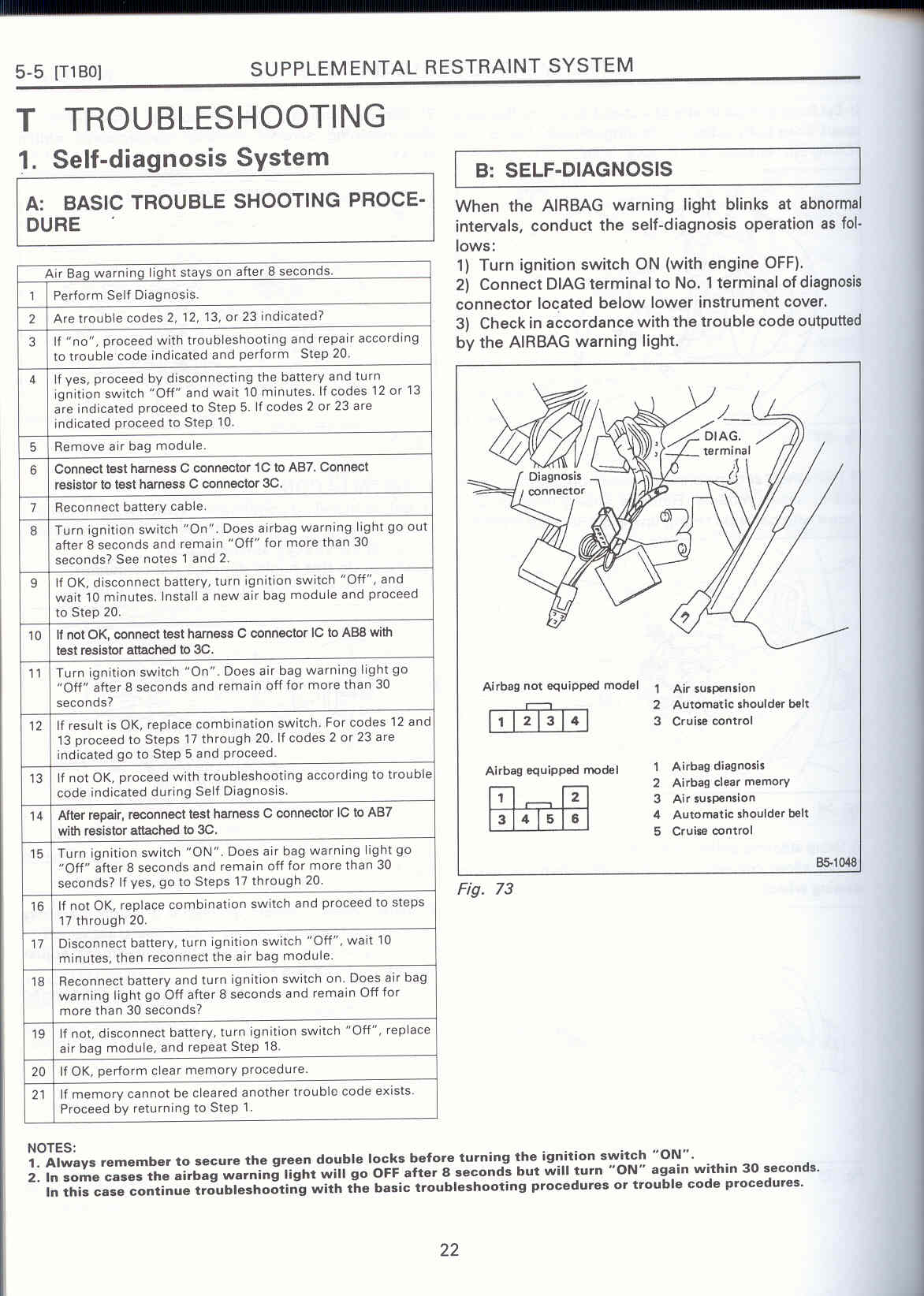
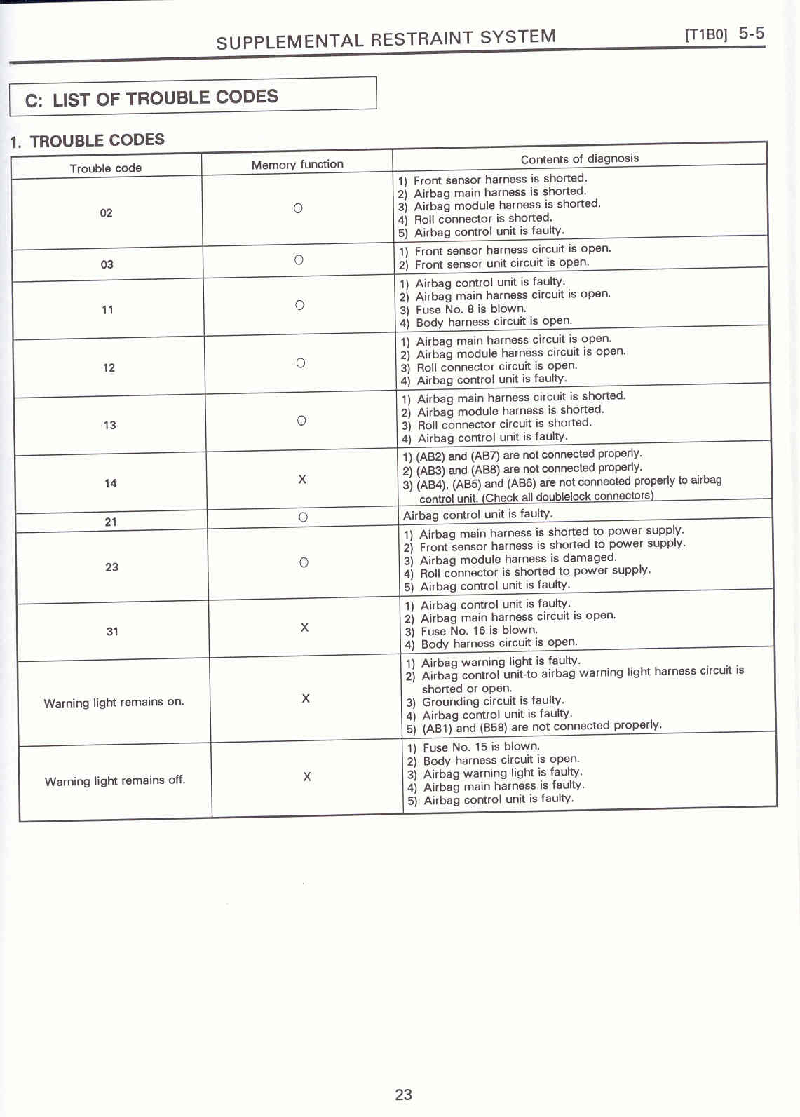
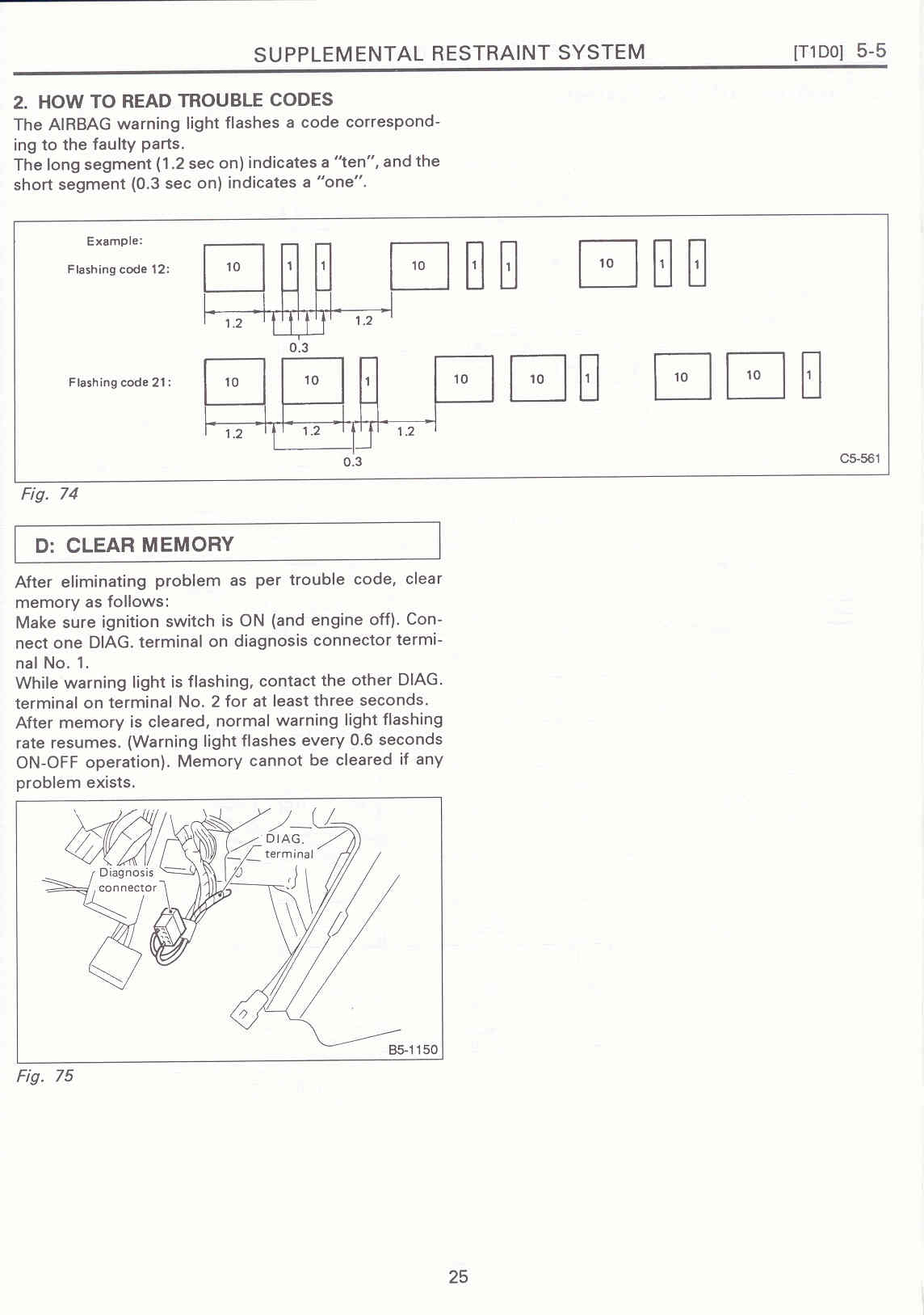
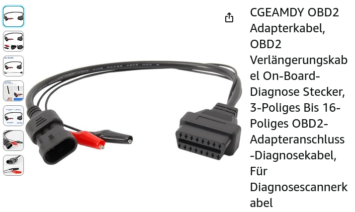
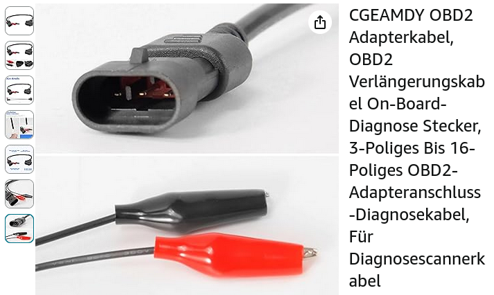
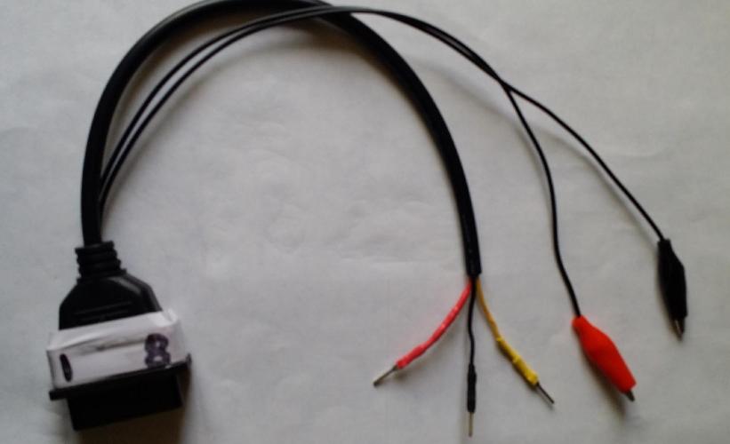
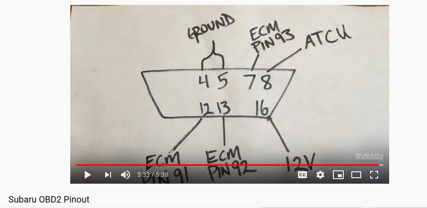